

You are using an out of date browser. It may not display this or other websites correctly.
You should upgrade or use an alternative browser.
You should upgrade or use an alternative browser.
Two MTM designs by Helmuth
- Thread starter Helmuth
- Start date
 this will become the end result.


Helmuth
Active Member
Excellent pictorial step by step of a DIY speaker design. You should be proud of the end product.
Thank for encouragement Ausjoe very appreciated. :thmbsp:
To morrow I will go to my colleague. And listen how they play there. I spend 100 hours to make and develop them for free. Because I want to see my idea's come to live.
And when you want to earn money on them people do not trust it. But when I made him happy is worth a lot.
Regards Helmuth
Last edited:

JoeESP9
ESL's & tubes since 83
Marvelous work and execution. If your colleague likes them a lot (I'm sure he will) that's the best advertisement you can get. Make enough speakers for colleagues and you may have a business based mostly on word of mouth. Although I'm a ESL person, I would love to hear your creations. The amount of care and thought you have expended could only result in superior sound. I especially like your approach to internal damping.
Helmuth
Active Member
Thanks Joe,Marvelous work and execution. If your colleague likes them a lot (I'm sure he will) that's the best advertisement you can get. Make enough speakers for colleagues and you may have a business based mostly on word of mouth. Although I'm a ESL person, I would love to hear your creations. The amount of care and thought you have expended could only result in superior sound. I especially like your approach to internal damping.
I work ad firm who makes electronics and there for got many colleagues how have audio as a hobby.
One of them made a booklet about self made ESL's about 25 years ago. I must say the midrange of a ESL is unbeaten and very natural. My colleague added a dome tweeter to his design due the poor of axes of the esl and a sub woofer.
I know the Final 1.2 and 1.4 fullrange esl very nice.
Helmuth
Active Member
Hi music lovers,
Yesterday I was at Pauls place to listen how the speakers sound at his place.
Was great, he has the same music taste as me. The room was small 4mtr and long 10mtr with high sealing. The high sealing had a positive effect on the sound stage.
It sounded big
I was interested in how the speaker at listening position measures compared to my own living room.
I must say I was surprised by the similarity of the results.
I post here my result I see never results of others I think every one measures the same poor results to the fact of flatness and so they do not dare to show them. But I have now problem with facing the reality, because the speaker is designed very well.
This is the result measured at the listening position about 3.5mtr from the speaker. Stereo MLS measurement. 1/3th octave. FFT window 85.3msec 4096 measurements. Used software HBX-V6 and calibrated omi mic EMC8000 16bit sound cart.

+5dB 22Hz-13kHz
If any one has problems with it show me your measurement at listening position stereo. And used software FFT-window and used filter to smooth. I am eager to learn.
Here is Paul my colleague how owns the speaker. He will write a review soon.

Regards Helmuth
Yesterday I was at Pauls place to listen how the speakers sound at his place.
Was great, he has the same music taste as me. The room was small 4mtr and long 10mtr with high sealing. The high sealing had a positive effect on the sound stage.
It sounded big
I was interested in how the speaker at listening position measures compared to my own living room.
I must say I was surprised by the similarity of the results.
I post here my result I see never results of others I think every one measures the same poor results to the fact of flatness and so they do not dare to show them. But I have now problem with facing the reality, because the speaker is designed very well.
This is the result measured at the listening position about 3.5mtr from the speaker. Stereo MLS measurement. 1/3th octave. FFT window 85.3msec 4096 measurements. Used software HBX-V6 and calibrated omi mic EMC8000 16bit sound cart.
+5dB 22Hz-13kHz
If any one has problems with it show me your measurement at listening position stereo. And used software FFT-window and used filter to smooth. I am eager to learn.
Here is Paul my colleague how owns the speaker. He will write a review soon.
Regards Helmuth
Last edited:


dnewma04
The Healer
Good job, Helmuth. It is not unusual to get fairly rough results like you are showing at a seating position. Is the room treated at all?
Also, can you change your scale on your y-axis to something more typical like a 50dB scale? When I first look at your graphs, I think they look relatively smooth until I convert them to 60-110dB scale and the issues appear more prevalent. It looks like you took steps to reduce diffraction by rounding over the edges, then placed the tweeters in a very distint and sharp valley.
One suggestion I would make is to avoid steps on the baffle that you have created. Time alignment can be accomplished in other methods, if you decide you want steps makes the smoothest transitions your tools will allow.
Also, can you change your scale on your y-axis to something more typical like a 50dB scale? When I first look at your graphs, I think they look relatively smooth until I convert them to 60-110dB scale and the issues appear more prevalent. It looks like you took steps to reduce diffraction by rounding over the edges, then placed the tweeters in a very distint and sharp valley.
One suggestion I would make is to avoid steps on the baffle that you have created. Time alignment can be accomplished in other methods, if you decide you want steps makes the smoothest transitions your tools will allow.
Helmuth
Active Member
Pauls untreated living room with wooden floor and sealing.Good job, Helmuth. It is not unusual to get fairly rough results like you are showing at a seating position. Is the room treated at all?
Also, can you change your scale on your y-axis to something more typical like a 50dB scale? When I first look at your graphs, I think they look relatively smooth until I convert them to 60-110dB scale and the issues appear more prevalent. It looks like you took steps to reduce diffraction by rounding over the edges, then placed the tweeters in a very distint and sharp valley.
My own livingroom with pauls speaker.

And now again but on the scale Dnewma asked for. Zoomed this way in it becomes unclear what the average behaivour is. It would be a good scale with very little variations but this is regretfully not the case.

That is the chosen design looks good and it compensates the phase shift of the filter, and Paul likes the look of it.One suggestion I would make is to avoid steps on the baffle that you have created. Time alignment can be accomplished in other methods, if you decide you want steps makes the smoothest transitions your tools will allow.
Then it stays the question if it helps improving the response.
Last edited:
Helmuth
Active Member
The bandpass sounded not as respected, and the solution was increasing the cross area off the bass reflex pipe.
Here a link to calculate optimum pipe.
http://www.diysubwoofers.org/misc/portcal.htm
37% bigger.
And it is 30% of the cone size. I use mesh wire to close the end so I prevent my kids to put in al their toys.

The effect better impulse behaivour tighter sound. The low response stays intact even at low spl. The low sounds warm and relaxed.
Personally I would like more dynamic bass. But I have to appreciate the good response at all levels.
Cheers, Helmuth
Here a link to calculate optimum pipe.
http://www.diysubwoofers.org/misc/portcal.htm
37% bigger.
And it is 30% of the cone size. I use mesh wire to close the end so I prevent my kids to put in al their toys.
The effect better impulse behaivour tighter sound. The low response stays intact even at low spl. The low sounds warm and relaxed.
Personally I would like more dynamic bass. But I have to appreciate the good response at all levels.
Cheers, Helmuth
Last edited:



Helmuth
Active Member
The speaker measure software makes use of the MLS technique.
The advantage of this technique is that you can do anechoic chamber measurement without anechoic chamber. The technique can discriminate the measured reflections by choosing the length of the FFT-window. So when the result is calculated the reflections do not interfere the result.
See this picture when you choose a gate length of 40ms the reflection is discriminated. When you choose a very short gate you can only measure high frequencies.
So this is a problem you can measure high very accurate even with your normal setup in your living room. To measure good low frequencies go measure in the open field like in the garden where are less reflections.

PDF about the MLS technique. http://www.mclink.it/com/audiomatica/download/cliomls.pdf
I use HBX V6 :http://www.speaker-online.de/hobbybox/
There is also good freeware ARTA:http://www.fesb.hr/~mateljan/arta/index.htm
And a nother popular program. Justmls :http://www.ijdata.com/
Regards Helmuth
The advantage of this technique is that you can do anechoic chamber measurement without anechoic chamber. The technique can discriminate the measured reflections by choosing the length of the FFT-window. So when the result is calculated the reflections do not interfere the result.
See this picture when you choose a gate length of 40ms the reflection is discriminated. When you choose a very short gate you can only measure high frequencies.
So this is a problem you can measure high very accurate even with your normal setup in your living room. To measure good low frequencies go measure in the open field like in the garden where are less reflections.
PDF about the MLS technique. http://www.mclink.it/com/audiomatica/download/cliomls.pdf
I use HBX V6 :http://www.speaker-online.de/hobbybox/
There is also good freeware ARTA:http://www.fesb.hr/~mateljan/arta/index.htm
And a nother popular program. Justmls :http://www.ijdata.com/
Regards Helmuth
Last edited:
Helmuth
Active Member
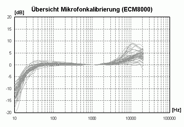
Calibration data of many behringer ecm8000 in this picture.
Another freeware program Holmacoustics.
http://www.holmacoustics.com/holmimpulse.php
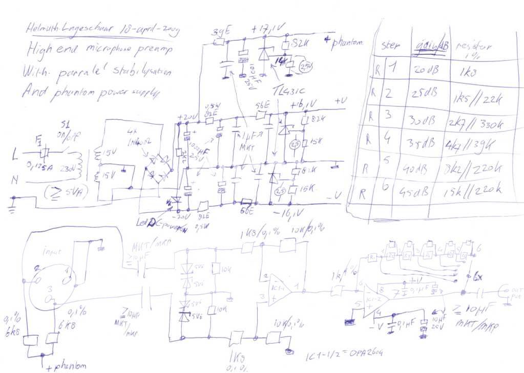
Linkwitzlabs mic and preamp DIY
http://www.linkwitzlab.com/sys_test.htm
Clio software http://www.audiomatica.com/
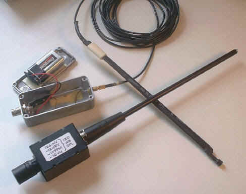
Another DIY measuremicrophone http://home20.inet.tele.dk/audio/Measurement_Mic/microphone.htm

Enjoy
Another freeware program Holmacoustics.
http://www.holmacoustics.com/holmimpulse.php
Linkwitzlabs mic and preamp DIY
http://www.linkwitzlab.com/sys_test.htm
Clio software http://www.audiomatica.com/
Another DIY measuremicrophone http://home20.inet.tele.dk/audio/Measurement_Mic/microphone.htm
Enjoy
Last edited:

Helmuth
Active Member
Here the review from Paul
:thmbsp:wow
Hi Helmuth, I would like to thank you once more for building me the best sounding pair of speakers I ever owned!
As you know, I wasn't satisfied with the sound of my Harman Kardon Festival surround stereo set with 5.1 JBL speakers!
At first I denied it but after a while it became very clear to me that I had to get rid of the annoying surrogate surround sound.
What a mistake did I make to ever buy one of those sets.
I was glad to hear that you preferred the large volume stereo speaker sound as well and think that you succeeded in defining the ultimate speaker sound for me. Well balanced high- and midtones, but a fat, yet precise base, because rock'n roll has to be in your face, right?!
The looks are great as well, I think that the light coloured berch wood combined with the black front with recessed aluminium tweeters and carbon fiber woofers really are an asset to my modern interior.
After a couple of weeks listening to them (poor neighbours!) in combination with my old JVC super A Amplifier, I have to say that I am very pleased that I can enjoy the "live" music experience again. As if I am in a concert hall with the musicians! Because of the well-defined and balanced tones I can also enjoy the sounds of various intruments floating into my living room. This would never have been possible with my budget had I bought speakers in a hifi store. Thnx 4 this and hope you can make many other people happy with your craftmanship!
I would be glad to recommend.
Best regards,
Paul
:thmbsp:wow
Hi Helmuth, I would like to thank you once more for building me the best sounding pair of speakers I ever owned!
As you know, I wasn't satisfied with the sound of my Harman Kardon Festival surround stereo set with 5.1 JBL speakers!
At first I denied it but after a while it became very clear to me that I had to get rid of the annoying surrogate surround sound.
What a mistake did I make to ever buy one of those sets.
I was glad to hear that you preferred the large volume stereo speaker sound as well and think that you succeeded in defining the ultimate speaker sound for me. Well balanced high- and midtones, but a fat, yet precise base, because rock'n roll has to be in your face, right?!
The looks are great as well, I think that the light coloured berch wood combined with the black front with recessed aluminium tweeters and carbon fiber woofers really are an asset to my modern interior.
After a couple of weeks listening to them (poor neighbours!) in combination with my old JVC super A Amplifier, I have to say that I am very pleased that I can enjoy the "live" music experience again. As if I am in a concert hall with the musicians! Because of the well-defined and balanced tones I can also enjoy the sounds of various intruments floating into my living room. This would never have been possible with my budget had I bought speakers in a hifi store. Thnx 4 this and hope you can make many other people happy with your craftmanship!
I would be glad to recommend.
Best regards,
Paul
Helmuth
Active Member
I made a simulation of the BR baffle with Boxsim ( freeware german)http://www.visaton.de/de/literatur/software/downloads/index.html.

Here is the final filter design of the Basreflex box.

And here the phase and impedance measurement of the bassreflex.

Here is the final filter design of the Basreflex box.
And here the phase and impedance measurement of the bassreflex.
Last edited:
Helmuth
Active Member
About the used capacitors in the filter design. The MKP types have very low absorption losses and there for the the best specs for a filter capasitor.
auricap
Een non inductive polypropyleen condesator auricap specificeerd dielectrical absorbsion shell not exceed 0.1% (een wima FKP 0.05%)
On Capacitor Dielectric Materials - A Chemist's View
Karl A. Weber, Ph.D.
The fundamental function of a capacitor is to store opposite polarity electrostatic charges on a pair of electrically isolated (insulated) conductive surfaces. The quantity of charge stored on each of these surfaces is ideally directly proportional to their surface areas and inversely proportional to the distance between the surfaces. Such a simple understanding needs to be refined to take into account the effect of the electric field set up between the charged plates on the insulating material. In theory this concern could be avoided by constructing capacitors without any material between: a vacuum.
Unfortunately, such high vacuum devices would be impractical. The next best insulating material is air since it provides limited interacting material and a very high resistance. Air is only practical for the lowest capacitances. Other insulating materials have included: paper/oil, minerals, ceramics, glasses, ceramic corrosion layers on metals and plastic films. Any insulating material used in capacitors of identical dimensions will increase the capacitance with respect to that of a vacuum.
The proportionality constant relating each material's capacitance enhancement over that of a vacuum is known as its "dielectric constant." The dielectric constant is a measure of the extent to which the insulating material's surface interacts with the electric field set up between the charged plates. The constant is dependent on two molecular level properties: the permanent "dipole moment" and the "polarizability" or the induced change in dipole moment due to the presence of an electric field. The permanent dipole moment is the average over the various dipole moments given rise to by structural charge density differences over intramolecular distances. The charge density differences result from the electronegativity differences between the various atoms which comprise the molecular structure of the insulator. Polarizability is the property which arises from changes in the molecular electron distribution induced by the applied electric field. Both of these properties contribute to a net field, of opposite orientation to the inducing electric field between the charged plates. The larger the dielectric constant, the greater the induced field on the surface of the insulating material or "dielectric."
In A.C. applications, where signal handling is involved, factors which affect the rates of both charging/discharging become key issues. Even though dielectrics with larger constants allow smaller size/capacitance devices, the properties of such dielectrics contribute deleteriously to audio signal processing. Where dielectrics with larger constants are employed, their larger dipole moments/polarizabilities interact more strongly with the inter-plate field, resulting in a stronger induced opposing field on the dielectric. When a capacitor is discharged across a load the polarized dipoles thermally relax in a statistical manner, exhibiting a time decay, observed as a tailing decay of residual current as complete discharge is approached. If the capacitor is suddenly discharged, allowed time to set and then shunted across a load it will discharge a residual current (of the same polarity as the initial charge). Upon dissipation of the bulk of the charge, the polarized dipoles on the dielectric thermally relax, which results in a residual charge on the plates. The residual charge from dielectric relaxation is known as the "dielectric absorption." When an audio signal is passed through a capacitor the dielectric absorption prevents full charging and discharging of the capacitor at the frequency of the alternating current signal. When the signal reverses the charging on the plates the dielectric absorption presents a lagging current of the former polarity, a hysteresis effect results. This effect becomes more acute with increasing frequency.
Obviously now, not all dielectrics are equal. In audio applications it is desirable to seek the insulating material with the lowest practical dielectric absorption; hence, lowest dielectric constant, barring size and economics. Dielectric materials can be classified based on their relative polarity/polarizability properties, which the dielectric constants and dielectric absorptivities parallel.
What follows is a qualitative categorization of dielectric materials in decreasing polarity/polarizability based on chemical structure considerations (Dielectric constant data "K" given when available):
I. Metal oxide corrosion layers (electrolytic capacitors):
1) Tantalum oxide (K = 11)
2) Aluminum oxide (K = 7)
Both consist of polar metal oxide bonds possessing large permanent dipole moments, polarizability factors are negligible.
II. Ceramics and Glasses:
1) Ceramics - typically alumina or aluminosilicates (K = 4.5 - thousands)
2) Glasses - typically borosilicate (K = 4-8.5)
Similarly, the polar inorganic oxide bonds in these materials have large permanent dipole moments.
III. Minerals:
1) Mica (most common) - an alkali metal aluminosilicate, hydrate (K = 6.5 - 8.7)
Same as II.
IV.
A. Polymer films - functionally linked - ranked in order of decreasing functional linkage polarity (brackets "[ ]" indicate guess based on functional group polarity):
1) Polyesters (ex. Mylar) - ester (K = 3.2 - 4.3)
2) [Kapton - ether and imide]
3) Polyamides (ex. Nylon) - amide (K = 3.14 -3.75)
4) Polycarbonate - carbonate (K = 2.9)
5) [PEEK - ether and ketone]
6) [Poly(phenylene oxide) - PPO - ether]
7) [Poly(phenylene sulfide) - PPS- thioether]
The members of the above list can essentially be ranked based on polarity considerations alone, though polarizability considerations are significant for the latter members of the list.
B. Polymer films - carbon chain backbone - ranked in order of decreasing attached-group polarity/polarizability:
1) Poly(vinyl chloride) - PVC - chloro-substituted (K = 3.3 - 4.55)
2) Poly(chlorotrifluoroethylene) - chloro- and fluoro-substituted (K = 2.48 - 2.76)
3) Poly(p-phenyleneethylene) - Parylene - exception to list phenyl ring in backbone (K = 2.65)
4) Polystyrene - phenyl-substituted (K = 2.54 - 2.56)
5) Polyethylene - essentially unsubstituted carbon chain (K = 2.3 - 2.37)
6) Polypropylene - methyl-substituted (K = 2.1)
7) Poly(tetrafluoroethylene) (ex. Teflon) - perfluoro-substituted (K = 2.0 - 2.1)
To rank the first two members of this list consideration must be given to both, polarity and polarizability considerations. Polymer 2) is adequately fluorinated to cancel C-F bond polarities, the C-Cl bonds are the prime contributors to its polarity. Since C-F bonds are not verypolarizable, polymer 1) has a higher polarizability than polymer 2) and a correspondingly higher dielectric constant. Polymers 3) and 4) can be ranked primarily on their polarizabilities, which are significantly higher due to the pi-electrons in their phenyl moieties. Polymers 5 and 6 differ mainly in that the methyl substituted chains are less prone to wrap against themselves due to steric methyl-methyl interactions. In Teflon the C-F bond polarities essentially cancel since it is completely fluorinated, and given that the C-F bonds are not very polarizable it exhibits overall less polarizability than its unsubstituted carbon chain analogue, 5), polyethylene.
Based on polarization/dielectric constant considerations for minimization of dielectric absorption, the best films for audio applications are teflon and polypropylene. Runners up would be polyethylene and polystyrene, based on these considerations alone. Throughout this discussion, I have assumed that dielectric absorption and the dielectric constant are directly correlated.
Apparently, when polarizability factors predominate, the time constant for relaxation of the field induced dipole is critical. Otherwise, one would expect polypropylene to have a lower dielectric absorption than polystyrene, which is not the observed result. This can be reasoned by re-examining what is being polarized by the field in each. In the case of the polystyrene, the pi-electrons in the aromatic rings (which have been modeled, in the past, as a "free electron gas") can orient electronically, with less mechanical change in the polymer structure. Hence, it can relax faster. In contrast, the polarization of polypropylene involves more mechanical change of the structure, and hence a slower relaxation rate.
Up to this point, I have only mentioned in passing paper/oil (paper-in-oil) capacitors. These classic devices from "days of yore" are making a comeback in some audio circles - especially among tube connoisseurs. Certainly, they are of interest. Unfortunately, they employ a composite dielectric that consists of a paper spacer/absorbent saturated with an oil; therefore, they do not readily lend themselves to the present simple analysis. Since the dielectric polarization primarily occurs on the surface of the dielectric material, in the vicinity of the plates, the dielectric constant in such a capacitor would consist of a weighted average of two dielectric constants: the most significant weighting attributed to the oil and the lesser weighting attributed to the surface area of the fibrules of paper in contact with the metal plates. The weightings for each dielectric component are not readily measurable. Hence, all that we know is that the contribution of the paper cannot be neglected, since it acts as a supporting spacer for the tightly rolled foil plates and makes intimate contact with them. One should measure the dielectric constant for each type of paper/oil combination under consideration.
The most common combination is that of a petroleum derived mineral oil absorbed into kraft paper. Common foils include aluminum and tin. More "exotic" variants on this theme, are those capacitors distributed by a certain manufacturer/distributor in England (who’s name shall remain omitted here), which consist of a vegetable oil/unspecified type paper dielectric and copper or silver foil plates. [It should be noted that the same British manufacturer also sells a series of mylar film (K = 4)/foil capacitors for signal handling: a pecular dielectric material for high cost/performance audio signal carrying applications.] The nature of the plate metal is not nearly as important as that of the oil and the paper. Mineral oils, consist mainly of saturated hydrocarbon oils and exhibit very low dielectric constants near K = 2. In contrast, papers such as Kraft paper exhibit dielectric constants on the order of K = 4. If we assume a mere 10% paper-plate contact, the composite dielectric constant would be near K = 2.2; which is similar to that of polypropylene. The 10% figure is merely an arbitrary suggestion. Unfortunately, one would expect two superimposed polarization thermal relaxation rates: that associated with the polar solid cellulosic paper would be significantly slower than that for the non-polar liquid mineral oil. In contrast, the relaxation rate for a non-polar polymer film such as polypropylene would be nearer that of mineral oil than that of paper; and its relaxation characteristics would be more uniform due to its homogeneous nature. The use of vegetable oil in place of the mineral oil only makes matters worse for the paper/oil composite dielectric; since vegetable oil, as a fatty acid ester, would exhibit a dielectric constant in the vicinity of K = 3. If we again assume 10% paper-foil contact, the composite dielectric constant would be near K = 3.1. (Perhaps such capacitors might be better suited for the culinary arts!)
Clarity SA clarity SA dielectrical absorbsion < 0,1% (wima FKP 0,05%)
The SA range of capacitors is now recognised as one of the best audiophile components currently available.
Specially developed to meet the needs of the professional audio engineer in both hi-fi and studio monitoring, these components are the result of extensive consultation between the audio industry and ClarityCap.
The capacitors are hand wound using a 10µm(630Vdc) rated polypropylene film. Following a special heat treatment cycle,insulated copper terminals are hand soldered to give the best possible connection.
The inherently low dissipation and dielectric absorption factors of polypropylene allied with an excellent mechanical stability results in an extremely detailed sonic performance. The construction also results in a low self-inductance and ESR and the devices are highly stable with regard to temperature and frequency.
Tape and resin colours are flexible with options shown in Custom products. Unless specified, capacitors would be supplied with black tape and black resin.
WIMA
Dielectric:
Polypropylene (PP) film
Capacitor electrodes:
Aluminium foil and double-sided metallized plastic film
Self-healing
Non inductive Internal construction:

Dielectric absorption: 0.05%
Last edited:
Helmuth
Active Member
Used drivers.
Monacor
Carbon subwoofer sph250ctc
http://www.monacor.de/typo3/index.php?id=84&L=1&artid=2071&spr=EN&typ=full
High quality 28mm dome tweeter DT300
http://www.monacor.de/typo3/index.php?id=84&L=1&artid=3260&spr=EN&typ=full

Mivoc
high quality horn tweeter xgh258alu
http://www.mivoc.com/mivoc/details-einzel.html?marke=mivoc&artikel=XGH%20258%20ALU
5" midrange polypropylene titanium sandwich.
http://www.mivoc.com/mivoc/details-einzel.html?marke=mivoc&artikel=WPT%20138
visaton
TI100
http://www.visaton.de/en/chassis_zubehoer/tiefmittelton/ti100_8.html
Vifa
pL26
http://www.tymphany.com/pl26wr09-04
Monacor
Carbon subwoofer sph250ctc
http://www.monacor.de/typo3/index.php?id=84&L=1&artid=2071&spr=EN&typ=full
High quality 28mm dome tweeter DT300
http://www.monacor.de/typo3/index.php?id=84&L=1&artid=3260&spr=EN&typ=full
Mivoc
high quality horn tweeter xgh258alu
http://www.mivoc.com/mivoc/details-einzel.html?marke=mivoc&artikel=XGH%20258%20ALU
5" midrange polypropylene titanium sandwich.
http://www.mivoc.com/mivoc/details-einzel.html?marke=mivoc&artikel=WPT%20138
visaton
TI100
http://www.visaton.de/en/chassis_zubehoer/tiefmittelton/ti100_8.html
Vifa
pL26
http://www.tymphany.com/pl26wr09-04
Last edited:


