

You are using an out of date browser. It may not display this or other websites correctly.
You should upgrade or use an alternative browser.
You should upgrade or use an alternative browser.
Using VHF TV Antenna for FM Radio ?
- Thread starter liemjerry
- Start date

Register to hide this ad


The VHF section of the antenna will probably have it's best reception at the middle of its range (approximately 139 mhz) so it will not be ideal but should work somewhat as long as it doesn't have an FM trap, as pointed out by vwestlife. It will also need to be aimed at the transmitters for best results.

k6sti
Active Member
TV channels 2-6 occupy 54 to 88 MHz while 7-13 are at 174 to 216 MHz. Some TV antennas cover these two bands but have poor response elsewhere. I have a VHF TV antenna that works really well in the first few MHz of the FM band adjacent to TV channel 6 but noticeably degrades higher in the band.
If all you need is local reception, any TV antenna is likely to work OK on FM. But if you want to receive weaker FM stations, you'll need a dedicated FM antenna. Directional FM antennas are no longer manufactured except for the Stellar Labs 4-element Yagi. It is a poor design with low gain and a miserable pattern. But it's cheap and it can be improved.

Here an additional element increases forward gain. You can construct the element and boom extension from a single piece of aluminum available at Home Depot. Details here:
http://ham-radio.com/k6sti/stellar.htm
A superior design of about the same size you can make from scratch with Home Depot parts is described here:
http://ham-radio.com/k6sti/five.htm
A much more ambitious design that uses Home Depot parts is this:
http://ham-radio.com/k6sti/depot.htm
Brian
If all you need is local reception, any TV antenna is likely to work OK on FM. But if you want to receive weaker FM stations, you'll need a dedicated FM antenna. Directional FM antennas are no longer manufactured except for the Stellar Labs 4-element Yagi. It is a poor design with low gain and a miserable pattern. But it's cheap and it can be improved.
Here an additional element increases forward gain. You can construct the element and boom extension from a single piece of aluminum available at Home Depot. Details here:
http://ham-radio.com/k6sti/stellar.htm
A superior design of about the same size you can make from scratch with Home Depot parts is described here:
http://ham-radio.com/k6sti/five.htm
A much more ambitious design that uses Home Depot parts is this:
http://ham-radio.com/k6sti/depot.htm
Brian

ConradH
Lunatic Member
I like this design- http://ham-radio.com/k6sti/omni.htm
I use heavy copper wire, thin wood crosspieces at the top and bottom with a Plexiglas plate in the center. I hang it from the center of the top piece. Or, you can use rigid tubing like they describe. It will work as badly as any other antenna in a poor location. Mine hangs on a wall in the basement, below ground. No doubt it would work better above ground.
I use heavy copper wire, thin wood crosspieces at the top and bottom with a Plexiglas plate in the center. I hang it from the center of the top piece. Or, you can use rigid tubing like they describe. It will work as badly as any other antenna in a poor location. Mine hangs on a wall in the basement, below ground. No doubt it would work better above ground.
An "FM Trap" is an electronic circuit that blocks the frequencies 88 - 108. Having an FM Trap on a TV antenna will not allow the FM frequencies you wish to receive to get to your tuner.anyone can explain whats the meaning of FM trap?
Last edited:
I found one locally, it was cheaper for me from the wholesaler than the Stellar Labs 4-element Yagi is from the distributor.Directional FM antennas are no longer manufactured except for the Stellar Labs 4-element Yagi.
I still need to mount it out side and test it since inside it does not work any better than the folded di-pole omni that works quite well mounted vertically. Now I know why it does after reading
http://ham-radio.com/k6sti/tilted.htm
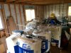
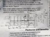
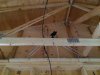
I will attach a few pics of these assembled and the physical measurements for the big 7 element yagi. Measurements are not much use, unless someone smarter than I, can use them for modeling the design. I'd be interested in how it performs.
Rick
Attachments
Last edited:
k6sti
Active Member
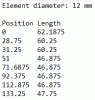
Rick, I modeled your antenna and posted results, but I deleted them since I wasn't sure of the dimensions. Please verify. Element position and length are in inches below. I assume element positions were measured between tubing centerlines, but that the length of the folded dipole was measured between the outer tubing surfaces. Is that right?
Brian
Brian
Hi Brian,
That is fantastic news that you will model this Yagi for us. Thank you
I was told that is a clone of an older Delhi design. It is mfg in China but seems to be well made. Only the weather will tell how well it holds up to the elements
I was going to attempt to put my measurements in a format you use for the AO program but you jumped on this task much faster than i expected
I held the tape measure clasp against the rear reflector (0 reference). I laid the tape measure across the top . measured the distances to the same point (back side or side closest to the rear reflector) on each element. The first director and rear reflector are in the same plane as the support. They are isolated from the Al support and have a Al strap underneath connecting the half elements together. All other elements are mounted on insulators above the support plane. I will get you those numbers since they must be important.
One thing I do not understand is that the elements ( other than the 1st director and rear reflector) are shorted to the Al support. The elements are mounted on plastic spacers above the support. they have steel machine screws in contact with the element and the screws run through the insulators and Al support with a nut in contact with the support. It is a DC short of the elements to the support.
I took many pics of the antenna assembly to show its construction. Will help explain what i wrote which can be confusing I will provide a link to them when I get on to my computer later today and update this thread with a link to the google cloud.
Hope I answered your ?’s If not I will provide you all the information you request.
Thanks again and have a nice day
Cheers
Rick
That is fantastic news that you will model this Yagi for us. Thank you
I was told that is a clone of an older Delhi design. It is mfg in China but seems to be well made. Only the weather will tell how well it holds up to the elements
I was going to attempt to put my measurements in a format you use for the AO program but you jumped on this task much faster than i expected
I held the tape measure clasp against the rear reflector (0 reference). I laid the tape measure across the top . measured the distances to the same point (back side or side closest to the rear reflector) on each element. The first director and rear reflector are in the same plane as the support. They are isolated from the Al support and have a Al strap underneath connecting the half elements together. All other elements are mounted on insulators above the support plane. I will get you those numbers since they must be important.
One thing I do not understand is that the elements ( other than the 1st director and rear reflector) are shorted to the Al support. The elements are mounted on plastic spacers above the support. they have steel machine screws in contact with the element and the screws run through the insulators and Al support with a nut in contact with the support. It is a DC short of the elements to the support.
I took many pics of the antenna assembly to show its construction. Will help explain what i wrote which can be confusing
I will provide a link to them when I get on to my computer later today and update this thread with a link to the google cloud.Hope I answered your ?’s If not I will provide you all the information you request.
Thanks again and have a nice day
Cheers
Rick
Hi Brian,
Thank you
Well that is just great that you did the analysis but bad in that it is not a very good performer for the length of the damn thing. They advertised this as a 72" LPA FM. I thought I'd try it in the attic of the loft but that won't work. I was surprised when I put it together, going this wrong, it is almost twice the length as they advertised
It is dirt cheap at the wholesalers price to me. I actually bought two of them because they were so cheap. I can not buy the Al bits at HD for what I paid for this antenna. Like you say, I might be able to "Or it might be a useful source of aluminum for a decent design."
I took a couple of pics of the element heights off the main support, not sure if that is important. Created a google drive showing numerous pics of the antenna if you need further information.
https://drive.google.com/drive/u/2/folders/1bzGUyd0e7ZV7vm6QRNqHGSRCH-kYQm20
I basically tune in a low power transmitter, CFGI (92.3MHz) but we have lots of good stations in my locale. CFGI is basically commercial free and excellent music, since they play what ever they want too. It is the Indigenous radio station for the Georgina Island reserve. They are putting out 450W, even though they are licensed for 650W. I know, because I repaired their Nautel transmitter, as a favour, this summer after the 48V PS blew. A real simple plug n play fix. They thought it was a big deal I was glad to help them out.
I live in a river valley hamlet. The transmitter maybe no more than 15-20 miles ( NNE as the bird flies) from me but there are hills in between. So direct line of site is not the best depending on the weather and time of day (sun). My T-85 and Si4735 radios have no problem in mono, but I get a lot of stereo noise since the signal is so low.
I have a old deep fringe VHF/UHF TV antenna on my tower ( with an amp up the mast) but the rotor is now seized, pointing N just off direct line of site to CFGI, but it is getting interfered by a transmitter in Owen Sound ( NNW, probably 80+ miles away) that over powers CFGI at certain times of the day. Damn Channel Master rotors only last 10 years if you are lucky. There is also another high power transmitter in Grand Bend(WSW) at 92.3MHz, which is about ~100 miles away.
The omni that I put up, positioned as a titled di-pole works pretty good for CFGI but the signal is still low and I get a fair bit of stereo noise, even with blend on.
Okay so there is my story, time to decide what my plans going forward. Any advise is greatly appreciated.
Rick
Thank you
Well that is just great that you did the analysis but bad in that it is not a very good performer for the length of the damn thing. They advertised this as a 72" LPA FM. I thought I'd try it in the attic of the loft but that won't work. I was surprised when I put it together, going this wrong, it is almost twice the length as they advertised
It is dirt cheap at the wholesalers price to me. I actually bought two of them because they were so cheap. I can not buy the Al bits at HD for what I paid for this antenna. Like you say, I might be able to "Or it might be a useful source of aluminum for a decent design."
I took a couple of pics of the element heights off the main support, not sure if that is important. Created a google drive showing numerous pics of the antenna if you need further information.
https://drive.google.com/drive/u/2/folders/1bzGUyd0e7ZV7vm6QRNqHGSRCH-kYQm20
I basically tune in a low power transmitter, CFGI (92.3MHz) but we have lots of good stations in my locale. CFGI is basically commercial free and excellent music, since they play what ever they want too. It is the Indigenous radio station for the Georgina Island reserve. They are putting out 450W, even though they are licensed for 650W. I know, because I repaired their Nautel transmitter, as a favour, this summer after the 48V PS blew. A real simple plug n play fix. They thought it was a big deal
I was glad to help them out.I live in a river valley hamlet. The transmitter maybe no more than 15-20 miles ( NNE as the bird flies) from me but there are hills in between. So direct line of site is not the best depending on the weather and time of day (sun). My T-85 and Si4735 radios have no problem in mono, but I get a lot of stereo noise since the signal is so low.
I have a old deep fringe VHF/UHF TV antenna on my tower ( with an amp up the mast) but the rotor is now seized, pointing N just off direct line of site to CFGI, but it is getting interfered by a transmitter in Owen Sound ( NNW, probably 80+ miles away) that over powers CFGI at certain times of the day. Damn Channel Master rotors only last 10 years if you are lucky. There is also another high power transmitter in Grand Bend(WSW) at 92.3MHz, which is about ~100 miles away.
The omni that I put up, positioned as a titled di-pole works pretty good for CFGI but the signal is still low and I get a fair bit of stereo noise, even with blend on.
Okay so there is my story, time to decide what my plans going forward. Any advise is greatly appreciated.
Rick
Last edited:
k6sti
Active Member
It sounds like rear rejection isn't important. Install the antenna as high as you can, aim it for maximum signal, and see what happens.
If you need more gain and are willing to optimize for a narrow frequency range, use your aluminum to build this:
http://ham-radio.com/k6sti/maxg.htm
It will yield a stronger signal than stacking the two antennas you bought. The frequency scaler is for 3/8" or 10 mm elements. You'll need to use a small frequency offset for 12 mm.
Good luck, Rick.
Brian
If you need more gain and are willing to optimize for a narrow frequency range, use your aluminum to build this:
http://ham-radio.com/k6sti/maxg.htm
It will yield a stronger signal than stacking the two antennas you bought. The frequency scaler is for 3/8" or 10 mm elements. You'll need to use a small frequency offset for 12 mm.
Good luck, Rick.
Brian
Last edited:
Hi Brian,
I have to confess, I messed up on the dimensions for that CCFM8 Yagi. Sorry
Repost them again and updated the cloud
Curious, how much of a difference it makes
One more time if you are up to it
Position Length
0 62
28.5 60.25
31 60.25
50.75 46.875
71.375 46.875
92 46.875
112.4375 46.875
133 47.75
Rick
I have to confess, I messed up on the dimensions for that CCFM8 Yagi. Sorry
Repost them again and updated the cloud
Curious, how much of a difference it makes
One more time if you are up to it
Position Length
0 62
28.5 60.25
31 60.25
50.75 46.875
71.375 46.875
92 46.875
112.4375 46.875
133 47.75
Rick
Attachments
Last edited:


