• The move to the new server is done. There are some software and database maintenance updates in process. This has us passing the hat around to help out. We appreciate any donations. Seriously, even a dollar helps. The payment page may be found here - https://www.audiokarma.org/support.html

What's next? - C-2301 restoration.

Very nice work, looking forward to some updates!

The non-signal path replacements will all be 'low' or 'ultra low' impedance electrolytics such as Nichicon PM, HE and Panasonic FR.

I just looked into Nichicon PM. I do not think I've ever used them. From the brief comparison they seem to be a bit bigger/beefier version of a PW. The PW is listed as a miniature version of PM. They seemed to have a longer life and higher ripple rating for the same capacitance/voltage. Does this sound about right? I'm thinking to include these for future builds space permitting where PW would be used.
 
Very nice work, looking forward to some updates!


I just looked into Nichicon PM. I do not think I've ever used them. From the brief comparison they seem to be a bit bigger/beefier version of a PW. The PW is listed as a miniature version of PM. They seemed to have a longer life and higher ripple rating for the same capacitance/voltage. Does this sound about right? I'm thinking to include these for future builds space permitting where PW would be used.
I've eyeballed up the UPM many times, and even got some of them on hand for my next "project" where they will fit in nicely for the current rating.
 
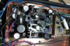
Here we have one channel of the MC Head Amp F-4471 PCB.

Before
IMG_3385a.jpg

After (in chassis but without screening plates refitted)
IMG_3389a.jpg

Update
C4 = 470µF, 50V - replaced with 470µF, 63V Nichicon PM
C6, C7 = 470µF, 50V - replaced with 470µF, 63V Nichicon PM.
C12, C13 = 470µF, 50V - replaced with 470µF, 63V Nichicon PW
C26, C27 = 1000µF, 50V - replaced with 1000µF, 63V Nichicon PM.
RL1 = Fujitsu D024/02CE - replaced with Omron G5V-2


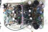
Here is one channel of the F-4472 EQ and Control Amp PCB

Before
IMG_3387a.jpg

After
IMG_3388a.jpg

Update
C34 = 470µF, 50V - replaced with 470µF, 63V Nichicon PM
C42, C43 = 470µF, 50V - replaced with 470µF, 63V Nichicon PW.
C51, C52 = 1000µF, 50V - replaced with 1000µF, 63V Nichicon PM.
VR2 = 4.7KΩ - replaced with Bourns 3296Y 4.7KΩ 25 turn trimmer.

(Control Amp)
C5 = 470µF, 50V - replaced with 470µF, 63V Nichicon PM.
C11, C12 = 470µF, 50V - replaced with 470µF 63V Nichicon PW.
C23, C24, C25, C26 = 1000µF, 50V - replaced with 1000µF, 63V Nichicon PM.
RL2 = Fujitsu D024/02CE - replaced with Omron G5V-2
VR1 = 4.7KΩ - replaced with Bourns 3296Y 4.7KΩ 25 turn trimmer.

I have just had the unit powered on again with all the boards present - all good, DC offsets adjusted very smoothly.

The completion of these boards means that the unit is about half done, Both regulated PSU's, one MC Head Amp, and one EQ/Control Amp are completed, which is the entire bottom tray. Leaving one MC Head Amp, and one EQ/Control Amp, the Protection PCB, and the Front Panel PCB.

Post now updated with component change information. ;)
 
Last edited:
Yep, not only are the suppliers running out of a lot of stuff due to high demand, but manufacturer's output has slowed due to COVID impact. My fear is that this situation might hasten the demise of more of our beloved 'through hole' components. :(
Don’t give them MORE excuses, John!
My last Mouser order, with their “2 day deliver at ground rates”, here in the States, took over 2 weeks to arrive. Usually, I have my order from them in 3 days.
My Digikey order, placed the same day, was here in 3 days.
But if the manufacturer’s lead times are increasing, we’re all screwed.
 
A Farnell order arrived today, so I was able to start work on one of the boards.

Here is a topside view showing the two power transformers (left) and the two MC step up transformers (right)
View attachment 2178855

Here a bottom view, pretty impressive isn't it ;)
View attachment 2178856

Here is a picture of the two regulated power supplies - the top one is untouched - the bottom one has replacement components.
View attachment 2178867

Update
C7, C8 = 100µF, 100V - replaced with 220µF, 100V Nichicon HE. (ESR so low it was unmeasurable = 0.00Ω)
C15, C16 = 47µF, 50V - replaced with 47µF, 63V Nichicon PM.
C17, C18 = 100µF, 50V - replaced with 100µF, 63V Panasonic FR. (ESR so low it was unmeasurable = 0.00Ω)
C21, C22 = 47µF, 50V - replace with 47µF, 63V Nichicon PM.
C23, C24 = 470µF, 50V - replaced with 680µF 63V Nichicon PM.

Some variations in the capacitor range above mostly caused by availability, and can size/lead spacing issues.

I have had to adopt a soft touch when it comes to removing all the Sansui glue because the solvent I am using reacts with the (black) sleeves of the very nice film capacitors. Sansui have also placed some glue to hold the two groups of three of these (on the right) together - so I dare not try to remove it for fear of damaging them. No glue will be allowed to remain in contact with component leads or other sensitive spots - (update) there is more than I thought in these locations. :(

My Mouser order has got as far as Memphis Tennessee..... and arrived after 9 days - normally takes 3 or 4 days.
Man, is that impressively integrated!
I can’t believe, though, that they used carbon comp resistors, rather than 1% metal films.
 
I've eyeballed up the UPM many times, and even got some of them on hand for my next "project" where they will fit in nicely for the current rating.
The UPMs have generally higher ripple current ratings than the UPWs, but that is what a bigger case gives you.
More surface area for the sandwich rolled up inside.
I’d expect them to have lower ESR, too.
But I didn’t look for that in the datasheet-I was specing power supply caps, so I wanted highest ripple current.
 
John, I see those boards look like they’re fabled on FR-4, rather than phenolic.
Do you happen to know when Sansui started using FR-4?
 
Man, is that impressively integrated!
I can’t believe, though, that they used carbon comp resistors, rather than 1% metal films.
Those blue colored resistors are high precision metal resistors. And back then, carbon comp performed just fine for their duty vs cost (bean counters ya know). But you can't always replace every resistor with metal film. Sometimes they are simply "too precise" and/or too "sterile" sounding.
 
Those blue colored resistors are high precision metal resistors. And back then, carbon comp performed just fine for their duty vs cost (bean counters ya know). But you can't always replace every resistor with metal film. Sometimes they are simply "too precise" and/or too "sterile" sounding.
The blue ones should be metal oxide.
Can’t beat ‘em for power applications.
Flameproof, small size/Watt ratings, and non-inductive.
Panasonic used to make a nice line of them, but they stopped producing them.

I mentioned metal films (1%) because they’re the lowest in voltage/current noise density.
Considering this is a pull-out-all-the-stops model, and that “warm Sansui sound” was a thing of the past, I’m surprised to see carbon comps, which are the noisiest, between carbon comp/carbon film/metal film.

It was my impression that the race to high bandwidth, high slew rate, and zero TIM kind of rendered a more sterile Sansui sound, from what I’ve read on AK.
 
Those blue colored resistors are high precision metal resistors. And back then, carbon comp performed just fine for their duty vs cost (bean counters ya know). But you can't always replace every resistor with metal film. Sometimes they are simply "too precise" and/or too "sterile" sounding.
Those are Riken resitors, one of the best ever made, modern equal class resistors are Amtrans

I was going to post about the resistors. I noticed they all looked very similar to the two that were replaced in my 919. I do not know the history of the 919 other than the guy I bought it from said the origional told him he had it serviced. The driver transistors on this side have also been replaced.

Are these the same resistors in the below photo? I remember they had little holes on the sides. Maybe this would mean it was serviced by a Sansui shop?

index.php
 
When I’ve used resistors with the tiny holes you mention, I was told they were vents.
I think the Panasonic metal oxides had those holes, too.
The two blue ones on the right ARE metal oxide.
I can’t recall ever seeing resistors like that, in a shiny case.
But, they are 2%-the two non the right are only 5%!
 
I took a look, and, yes, the ones on the left look like what I just saw online, searching for Riken resistors.
I also saw a blurb about carbon comp resistors being prized by audiophiles for their golden tone.
So, that MIGHT explain it.
 
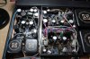
Here is a 'before' picture of the upper tray boards, the MC Head Amp (# two) on the left (with screens removed) and the EQ/Control Amp (# two) on the right.

IMG_3390a.jpg


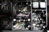
And now an 'after' picture (from the opposite direction), screens installed and all connections made.

IMG_3393a.jpg


Component change details are exactly the same as for MC Head Amp (one) and EQ/Control Amp (one). ;)

I set the DC offset adjustments, and verified all inputs are working - I discovered the extreme sensitivity of the MC Head Amps in a roundabout way while making checks - at first I thought they were faulty, but it was just pickup from my meter leads. ;)

I tested it last night and it sounds wonderful, the imaging and micro detail are astonishing, clearly this pre-amp is in a class of its own.

Now, for the last remaining items, namely the F-4474 Protection Board, and the F-4473 Front Panel Board, including the lighting PSU and controls.
 
Last edited:
As I was about to replace the capacitors on the Protection Board - look what I found - see the solder joints inside the red ring - dry!

IMG_3396a_ringed.jpg

The 2 pin ground connector actually fell out of the board as I was positioning the board for component removal. Needless to say the F-4474 Protection Board is now finished, the dry joints have been remade and the track side has been cleaned. I have also changed the 2 capacitors for the lighting supply on the F-4473 Front Panel Board, so there are no more components to be changed. ;)

The component change details for the F-4474 Protection Board are as follows:-

C1, 470µF 16V - replaced with 470µF 25V Nichicon PM.
C26, C29, 100µF 50V - replaced with 100µF 63V Nichicon PM.
C27, 47µF 50V - replaced with 47µF 63V Nichicon PM.

The component change details for the F-4473 Front Panel Board are as follows:-

C32, C33, 1000µF 16V - replaced with 1000µF 25V Nichicon PM.


I give you...

IMG_3397a.jpg

:)
 
Last edited:
Here is a 'before' picture of the upper tray boards, the MC Head Amp (two) on the left (with screens removed) and the EQ/Control Amp (two) on the right.

View attachment 2191141


And now an 'after' picture (from the opposite direction), screens installed and all connections made.

View attachment 2191142


Component change details are exactly the same as for MC Head Amp (one) and EQ/Control Amp (one). ;)

I set the DC offset adjustments, and verified all inputs are working - I discovered the extreme sensitivity of the MC Head Amps in a roundabout way while making checks - at first I thought they were faulty, but it was just pickup from my meter leads. ;)

I tested it last night and it sounds wonderful, the imaging and micro detail are astonishing, clearly this pre-amp is in a class of its own.

Now, for the last remaining items, namely the F-4474 Protection Board, and the F-4473 Front Panel Board, including the lighting PSU and controls.
Oke I know I am a little slow. But. . .
This is a X-balanced pre amp!?
Now I understand all those boards. . .
Mhh, now I am a lot more interested.
 
Now I know what John means by “dry solder joints”.
They shouldn’t have ever left the factory, with that little solder!
The angle of the picture conceals that fact that there is a convincing fillet of solder behind each pin, the problem is the solder hasn't 'taken' (perhaps due to oxidisation on the pins when originally assembled). This would have fooled a final assembly inspector at the factory as that is all he could see - the top edge of that board, but as you say, it should never have got that far. ;)

Only one pin of that connector is used and is a ground connection to the Protection Board via a 10,000pF capacitor.
 
Back
Top Bottom