

You are using an out of date browser. It may not display this or other websites correctly.
You should upgrade or use an alternative browser.
You should upgrade or use an alternative browser.
Yamaha A1 restoration 2021
- Thread starter Hifibythekg
- Start date
Hifibythekg
Super Member
Readings and photos of
TR 519 front and reverse.
C523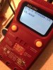


TR 519 front and reverse.
C523

BUT the SM states:
R549 56,000 ohms
R547 47,600 ohms
R548 47,000 ohms
R550 56,000 ohms
Emitter resistors test ok (not open)
FR503, D509, 511, R531, R543 seem ok
R547 and R549 are in parallel, also in parallel with C515.
In circuit measurements can be tricky due to alternate paths for
(MM) current flow. When you attempt to measure you are measuring
the total of the 3 above components, ie, 47k in parallel with 56k
gives 25.5k then in parallel with C515 gives??? Also note that
R547 and R549 gives the same result (16.6k), no issue there.
C523 tests ok however I'd replace since you've removed it, MKP or MKS film
I'm not seeing how -I can be +4.7V to +8.7V. The obvious path is via +I and
the bias cct. Double check voltages at +I and -I, monitor voltages for 2-3 minutes
careful with +/- sign.
Maybe consider replacing TR519 2SC1953 ecb with KSC3503 ecb.
Monitor voltage at D511 anode (TR519base)
Hifibythekg
Super Member
Thanks MBZ, and appreciate the working explanations.
Later I'll get on to this. In stock I have one KSC3503D, that should be fine?
Later I'll get on to this. In stock I have one KSC3503D, that should be fine?
Hifibythekg
Super Member
Just tested voltages at +I and -I.
At start up getting:
+I +454mV
-I -448mV
After a few minutes have passed:
+I has risen to +484mV
-I has dropped to -421mV
Haven't yet replaced TR519 2SC1953.
Should I still do so?
At start up getting:
+I +454mV
-I -448mV
After a few minutes have passed:
+I has risen to +484mV
-I has dropped to -421mV
Haven't yet replaced TR519 2SC1953.
Should I still do so?
Voltages look fine, suggest problem is intermittent, makes fault finding "fun".Just tested voltages at +I and -I.
At start up getting:
+I +454mV
-I -448mV
After a few minutes have passed:
+I has risen to +484mV
-I has dropped to -421mV
Haven't yet replaced TR519 2SC1953.
Should I still do so?
Wait on replacing any parts, TR519 would be a candidate if +/-I voltages were negative. Difficult for me to see
how -I pin is +ve and -I > +I voltage. When problem next occurs need to carefully check +/-I pins. If both neg 2-8V
then replace TR519, KSC3503D is ok. If +/- pins are both pos 2-8V and -I pin > +I then need to look elsewhere maybe
a solder bridge or similiar...
Hifibythekg
Super Member
Thanks MBZ.
My gut feeling is that I mistakenly wrote
- I 4.8V to 8.7V
Should probably have been
- I 480mV to 870mV
but will do more checks.
Bias reading between TP1 and TP3 remains at 0.00mV and doesn’t respond to adjusting the Bourns VR. Makes me think that a solder bridge or similar is at fault. If so, should I be looking solely at the Drive board or the Elec Cap board?
My gut feeling is that I mistakenly wrote
- I 4.8V to 8.7V
Should probably have been
- I 480mV to 870mV
but will do more checks.
Bias reading between TP1 and TP3 remains at 0.00mV and doesn’t respond to adjusting the Bourns VR. Makes me think that a solder bridge or similar is at fault. If so, should I be looking solely at the Drive board or the Elec Cap board?
Hifibythekg
Super Member
Once I know, I can start comparing Left and Right channel soldering with forensic attention..
What is the voltage TP1 to GND?Bias reading between TP1 and TP3 remains at 0.00mV
Hifibythekg
Super Member
On power up it starts at -36.5 mV and decreasing very slowly. Eg, -33.1 mC after a couple of minutes.
This is with red lead on TP1 and black lead on Ground / Chassis.
This is with red lead on TP1 and black lead on Ground / Chassis.
-I needs to be a/near negative voltage for correct control of driver TR136. The variation in voltages may be causedMy gut feeling is that I mistakenly wrote
- I 4.8V to 8.7V
Should probably have been
- I 480mV to 870mV
but will do more checks.
by TR136 toggling between "off and on". With the multi-turn trimmers you can get lost/confused which way to turn
the adjuster. Try monitoring the -I voltage along with TP1,3 and adjust the trimmer so the -I reduces to zero then goes negative. Somewhere -400mV would be nice through noticed right channel was only -50mV.
Hifibythekg
Super Member
Since the last update I’ve thoroughly cleaned and checked for solder joins etc on the left channel of the Drive board.
TP1 to Ground/ Chassis now reading -20.5mV
TP1 to Ground/ Chassis now reading -20.5mV
Use black speaker post for GND connection. Think it was avionic who posted that circuit GND was connected to chassis via a cap.On power up it starts at -36.5 mV and decreasing very slowly. Eg, -33.1 mC after a couple of minutes.
This is with red lead on TP1 and black lead on Ground / Chassis.
Hifibythekg
Super Member
"Use black speaker post for GND connection."
Sure, will do.
Also, I can't see TR136 anywhere on the diagram.. apologies if it's really obvious.
Sure, will do.
Also, I can't see TR136 anywhere on the diagram.. apologies if it's really obvious.
Hifibythekg
Super Member
BTW, just before changing Ground location, the TP1 to TP3 reading is now down to - 3.1mV
Hifibythekg
Super Member
O, and still with the same connection, it's climbing.. now at -12.2mV but hovering there..
Anyway, I'll get on with the other tasks.
Anyway, I'll get on with the other tasks.
Hifibythekg
Super Member
"Try monitoring the -I voltage along with TP1,3 and adjust the trimmer so the -I reduces to zero then goes negative. Somewhere -400mV would be nice through noticed right channel was only -50mV."
So,
Black lead on negative speaker post.
On Elec Cap board..
Red on -I.
Turn Bourns VR102 which will adjust the Right Channel which is already working OK-ish.
Correct?
So,
Black lead on negative speaker post.
On Elec Cap board..
Red on -I.
Turn Bourns VR102 which will adjust the Right Channel which is already working OK-ish.
Correct?
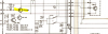
My mistake, good pickup. Left channel is faulty. Red probe on -I on left channel (near LO), adjust VR101Black lead on negative speaker post.
On Elec Cap board..
Red on -I.
Turn Bourns VR102 which will adjust the Right Channel which is already working OK-ish.
Correct?
EDIT: Driver TR135 on left channel may be shut down.