Follow along with the video below to see how to install our site as a web app on your home screen.
Note: This feature may not be available in some browsers.
The move to the new server is done. There are some software and database maintenance updates in process. This has us passing the hat around to help out. We appreciate any donations. Seriously, even a dollar helps. The payment page may be found here - https://www.audiokarma.org/support.html
Bias/TP1,3 still 0mV?
If yes then post all voltages on left channel, ie, LO, +I, -I,,CE, CC
Wanting +O, -O at about +/-1V. Need to step out for short time.
More typos in the sm??? Seems like TP1,3 associated with R-channel which is "wrong"
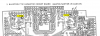
Need TP's closest to LO pin, marked TP2,4 below, vaguely recall markings on board have been corrected.
Signing off,
check left channel bias, test points closest to LO pin.
If still no response/0mV to VR101 then record left channel voltages with black mm probe connected to black spkr post
LO -18.5mV
-767mV..... +I +767mV
-419mV..... -I
-O -1006mV
+O +1359mV
-E -13.5mV
+E -14.3mV
AE -395mV....AB
CB 793mV
AE 5.2mV
AC -54.3V
CE -6.6mV
CC 53.8V
Little odd that CE is -ve and AE is +ve
CE should be same as +E
AE should be same as -E
CE to AE shows 11.8mV across emitter resistors while +E to -E shows 1mV
Seems like a disconnect between CE/AE and +E/-E.
With amp powered off try continuity/resistance check between CE and +E.
Repeat for AE and -E. Expect about 1 ohm in both cases.
CE to LO (1 emitter) shows 12mV, this is the same as measuring bias across the TP's
ie, meter should display 12mV at bias TP's. Check/reflow solder connections on jumper J123
(red), CE and AE wires and also at left channel TP's.
Seems like the amp is roughly biased(11.8mV) when using CE to LO but not ok when
using the TP1&3. Try to set bias (7.4mV) when connected to CE & LO (use minni grabbers)
Thank MBZ. So, today's initial measurements are..
CE -13.5mV
AE -13.4mV
+E -13.3mV
-E -13.4mV
these are all moving a bit, measurements taken about 5 mins after power on.