• The move to the new server is done. There are some software and database maintenance updates in process. This has us passing the hat around to help out. We appreciate any donations. Seriously, even a dollar helps. The payment page may be found here - https://www.audiokarma.org/support.html

Yamaha A1 restoration 2021

Update:

The amp was functioning and sounding very good..

Fitted the Bourns trimmers, wonderful improvement!
Power supply reads 35.2V
DC offset 0mV and stable.

Two problems:

1.
The left channel made a slight static scratch when either the ‘tone defeat’ or the ‘Disc’ was pressed on and off.
Then.. it made big scratchy sound on the left speaker.., I switched off the amp, and now the power button lights up but the speaker relay won’t activate.

What should I probably check for first?


Just prior to this however..
2.
No idling current adjustment on one channel.
Between TP2 and TP4 I can set a stable 7.4mV
But between TP1 and TP3 it’s about 0mV. No amount of turning the new pot will affect the reading.
Thought it might be some bad contact with the DMM but turning up the volume makes the idling current immediately climb up into the teens.
Have already changed TR 137 and TR138 from a 2SC1213A to a KSC2383, and TR 139 and TR 140 from a 2SA673 to a KSA708C.
Diodes 103 and Diode 104 replaced.
Checked solder joints.
Any suggestions anyone?
 
Finished replacing the speaker push pull switch but this hasn’t solved anything.

Followed your advice MBZ. I think the mV on the TP1 to Earth went way above this when the amp was switched on.
After a few seconds there was a very loud scratch/static through the left speaker. It just made me want to immediately switch off the amp, which I did.

If I first discharge the big caps is there anywhere I can look to investigate / repair / reset things rather than switching on again with the behaving like this?

Such a shame, as so much was repaired, refined and sounding very good.
The only remaining problem had been the inability to adjust the idle current on the left channel between TP1 and TP3.
 
the mV on the TP1 to Earth went way above this when the amp was switched on.
At power-ON, start up transients will result in unusual votages that take a few seconds to settle, TP1 voltage may go to Volts (not mV) depending on sampling rate of MM. Should settle in about 3 seconds.

I wouldn't be connecting good spkrs to the amp, use something disposable, eg, an old driver to problematic L-channel
With this setup and the amp making noise, you could try freeze spray, start with the power amp transistors, though problem could be anywhere since mostly direct coupled.

The only remaining problem had been the inability to adjust the idle current on the left channel between TP1 and TP3.
"Numbers" (voltages) are needed, voltages at the marked solder blobs would be a great start (probe blobes with wires attached).
upload_2021-10-11_7-14-18.png

Suggest monitoring the +I pin next to LO while adjusting the bias VR, need to adjust for +0.5 to +0.7Vdc
 
Thanks MBZ.
Will connect disposable speakers but haven't got any freeze spray at this time.
- If I switch the amp on in this state, am I likely to damage further components, or should a fuse blow before this can happen?
- For all the yellow highlighted solder blobs in the diagram, does one keep the negative probe attached to chassis/Earth and then touch the positive lead of the DMM to each of the blobs in turn?
 
does one keep the negative probe attached to chassis/Earth and then touch the positive lead of the DMM to each of the blobs in turn?
Yes
Test points on left channel (LO...) are more important, test points on right channel for comparison.

If I switch the amp on in this state, am I likely to damage further components, or should a fuse blow before this can happen?
Little hard to say as symptoms are a bit vague. Possibly a component is breaking down, leaking voltage which appears on the
spkr line in bursts. That component will in time permanently fail rather than blown fuse. Permanent failure will make troubleshooting easier rather than intermittent fault. If noise is reasonably constant (every 1-5 seconds) then I'd wait for the freeze spray, if noise is like once every 30 seconds (then you don't know the spray has "worked") then I'd press on with voltages. Note, voltages should be stable, note any unstable test points/voltage range.
 
Phew, lots of v loud crackling but only through the left speaker. Relay would cut in and cut out throughout.
Voltages very unstable, just ranging up and down so actually quite hard to keep track and record.
Right channel all very stable.
It's late now and I'd rather not give somewhat unreliable readings, but
I think:
LO flickered from 0 -12V
+I flickered 0 -18V
-I flickered 0 -35V
+ I flickered 0- 16 mV 20 seconds later.

+O flickered 0 -16V
-E 400mV
+E 400mV
...
AE 4 mV
AC 3mV
CE -40mV to +66mV
..
CC 3mV

but bear in mind that the relay was cutting in and out and this might have changed any given reading if it had occurred 20 seconds later.
Will attempt again tomorrow..
Thanks again.
 
  • Like
Reactions: mbz
Need to be careful with the +/-sign of the voltage, black probe connected to black
spkr post.

Your measurements suggests these are bursts which would be difficult to measure on my
el-cheapo MM due to the sampling frequency. Remeasure Vdc at LO, and confirm sign of
bursts (+ve?). Then with black probe connected to -I pin and red probe to +I pin
(use mini-grabbers or similiar) note the sign (+/-) of the bursts. Expect only 1-2Vdc
since -I and +I are connected via VR101 and R105.

If the +/-I bursts were +ve then maybe TR525, TR517, TR513,,,. -ve bursts would point to
TR527, 519,,, Could be something obscure like C523, 519, 51,,, breaking down

Freeze spray is going to be the quickest method..
 
On the PS board there are two transistors. I believe one is the power supply for the speaker relay. Check to see if the transistors are screwed tightly to their heat sink.

Also Re check the emitter resistors on the channel that will not adjust. Might have blown that again.

Athanasios
 
Last edited:
Greetings everyone!

After a while the amp wouldn’t even power on..

Checking every solder join etc etc I discovered that the red lead connected to LO on the Elec Cap board had frayed and severed!

Resoldered the connection and it now happily powers on, functions and plays music from a digital radio source via AUX input into crappy speakers.

Have connected two 8ohm 100W heatsinks (not 70W as per the Service Manual) volume at zero.

- DC offset ranges consistently up and down on both channels as follows:
TP1 - TP3 3.9mV to 13.2mV
TP2 - TP3 -2.6mV to 16.8mV

- PS voltage at TP1-TP0 is 35.0mV and stable.

Two problems or quirks remain:

Problem 1
- Idle Current:
Right 7.4mV and stable.
Left -0.7mV but adjusting VR does not change the reading. Turning up the volume control does increase the reading immediately, but it falls and readjusts to the previous levels very quickly.

Problem 2

If one slowly depresses the ’Tone’ push pull switch with a source connected to Aux while the volume is at zero so consequently no sound through the speakers the following occurs..
Midway on the push or pull, (i.e. neither Tone neither On or OFF) and with volume set to ZERO, sound at a lowish level plays through both speakers and a reading of about 13.4mV reads on the IDLE CURRENT TP1- TP3.
No such surge occurs on TP2-TP3.

With Tone at fully ON or OFF it reverts to a stable -0.7 mV. (Black lead to TP1 Red lead to TP3.)

Doing the same but with leads attached to DC Offset:
TP1 - TP3 the current shoots to 233mV during the inbetween stage!
TP2-TP4, no such surge occurs.


Apologies, for not yet taking new readings from the Elec Cap board points outlined in yellow previously.
Do the above readings give any clues, and do you still need the Elec Cap board readings to diagnose?
Many thanks.
 
Before replacing any parts suggest you get the amp working normal. Taking a baseline is also worthwhile, carefully measure dc voltages to GND/chassis at the highlighted pins (hint:measure at wire connections). The amp is mostly direct coupled, this makes
troubleshooting a bit difficult (still got bruises on my butt from 2 of my A1's)
View attachment 2344379

Here are the readings:

LEFT CHANNEL (FAULTY)

+O 450mV to 1000mV the reading ranges slowly up and down the scale.
But buy slowly depressing 'Tone' the reading can surge to 13.5V between being selected or not selected.

CC 54.2mV
CE 0mV
AC -54.2V
AE 0mV
CB 220mV to 810mV the reading ranges slowly up and down the scale.
AB 430mV to 912mV the reading ranges slowly up and down the scale.
+E 19.5mV
+O 450mV to 1000mV the reading ranges slowly up and down the scale.
-O 5.3V to 8.2V
- I 4.8V to 8.7V
+I 330mV to 650mV the reading ranges slowly up and down the scale.

LO 11.0mV to 19.99mV the reading ranges slowly up and down the scale.
+50 53.8V
+35 34.8V
+35 34.8V
-35 -35.0V
-35 -35.0V
-50 -53.9V

RIGHT CHANNEL

CC 54.8V
CE 0 mV
AC +54.5V stable
AE 0 mV
CB +573mV stable
AB +580mV stable
+E -550mV stable
+O 11.1mV to 32.2mV the reading ranges slowly up and down the scale.
-O -3mV to 14.1mV the reading ranges slowly up and down the scale.
- I -54mV stable
+I +52mV stable
LO 0mV stable

+50
+35
+35
-35
-35
-50

Will have to call it a day at this point. Do say if you need the last six readings from the right channel or if you want something double checked.
 
  • Like
Reactions: mbz
Will take a bit of time to digest measurements.

Looking at the left channel bias issue.
Minor typo CC, expect 54.2V not mV

Certainly -O and -I stand out as wrong or should these be mV?
Will have a look later in the day, others welcome to chime in...
 
Thanks MBZ, v reassuring to know that you're inwardly digesting.
Yes, CC is a typo it should have been 54.2V.
Problematic, no VR control channel 5 mins after startup today is:
- I -0.43V to 3.01V ranges up and down fairly rapidly. Seems to always be at the high end when I coonect the test lead and then begins the descent.
-O -1.08V to 2.4V
Both have an erratic quality. Might attach probes at other times or extended intervals and observe slightly greater variation.
 
Left channel bias issue.

- strange that both CE and AE are 0mV, are emitter resistors ok?
Measure R113,5 in circuit is fine, expect maybe 1ohm (includes MM probe/leed resistance)
Expect just a timing thing.


Thinking out loud so others can correct me...

AB voltage is too high so no bias current. Maybe some leakage through TR135 being the
source of this (+ve) voltage

-O and -I are the standouts, these should be -ve mV.
-I is the culprit however don't see a leakage path through bias complex(TR137,9 R105,,,)
D519(+I,+E,LO voltages) or C523 so probably TR519 with D511 and/or R531 or FR503 open

Suggest check FR503(47ohms) in circuit ok, expect open. Also check D511 and R531.
 
Hey MBZ, thanks for thinking out loud.

Please could you take a look at the discrepancy between the resistors on the circuit board compared to the SM, printed in bold below.
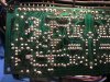
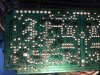
Have attached photos of the front and back of this area of the Drive pcb.

So,

R 113, 115 are 0.5ohms in circuit (0.8 when leads are added.)

FR 503 reads 47.4ohms
FR 503 reads 63 with DMM on 'diode test' setting.

D511 614 on diode test setting in circuit
D509 614 on diode test setting in circuit
Both test ‘I’ with leads reversed.
D507 reads 722 ‘I’ with leads reversed.

R531 reads 3,290 ohms
R531 reads 1538 on diode test setting in circuit (1545 with leads reversed.)

R549 reads 16,600 ohms
R549 on Diode test setting reads (1150 and 1720 with leads reversed.)

R547 reads 16,600 ohms
R547 on Diode test setting reads (1235 and 1720 with leads reversed.)

R543 reads 468
R543 on Diode test setting reads (497 and 498 with leads reversed.)

s
By contrast Right channel:

FR504 48ohms
FR504 reads 63 with DMM on 'diode test' setting.

D508 reads 722 ‘I’ with leads reversed.

R548 16640 ohms to 16680 ohms ranges quickly up and down (diode 1140 and 1090 leads reversed)
R550 16600 to 165600 ohms ranges quickly up and down (diode 1115 and 1090 leads reversed, although both were climbing slowly)
R532 3360 ohms (diode 1549 and 1530 leads reversed)
R544 470 ohms (diode 499 and 499 leads reversed)

BUT the SM states:
R549 56,000 ohms
R547 47,600 ohms
R548 47,000 ohms
R550 56,000 ohms
 
From the Service Manual
 

Attachments

  • Screenshot 2021-10-15 at 12.37.45.png
    Screenshot 2021-10-15 at 12.37.45.png
    871.8 KB · Views: 3
  • Screenshot 2021-10-15 at 12.35.33.png
    Screenshot 2021-10-15 at 12.35.33.png
    980.4 KB · Views: 2
Back
Top Bottom