

You are using an out of date browser. It may not display this or other websites correctly.
You should upgrade or use an alternative browser.
You should upgrade or use an alternative browser.
Yamaha A1 restoration 2021
- Thread starter Hifibythekg
- Start date
Hifibythekg
Super Member
Thanks for your patience guys.
On the side of the pub that has TP2 and TP4:
+I reads 540mV
+O “ 1.1V and switching the Speaker button on and off has no effect on the readings. However, turning the trimpot has a clear and direct effect on the readings.
On the side of the pub that has TP1 and TP3:
+O reads 1.1V This is with ‘Speaker’ button off, and volume at zero. Very stable throughout.
However, with Speaker button ON, it steadily climbs to approx 16V, then falls again.
Climbs up and down between approx 10V to 17V. Adjusting the pot has no effect on the readings at this time with Speaker button on and illuminated.
+I reads 540 mV This is with ‘Speaker’ button off, and volume at zero. Very stable throughout.
However, with Speaker button ON, it steadily climbs to approx 13V, then falls again.
Climbs up and down between approx 6V to 13V. Adjusting the pot has no effect on the readings at this time with Speaker button on and illuminated.
Audio output from the amp still sounds pretty good and I believe that I’m getting a reasonable stereo output, at least it doesn’t immediately sound unbalanced and different through the channels surprisingly given the readings issue.
On the side of the pub that has TP2 and TP4:
+I reads 540mV
+O “ 1.1V and switching the Speaker button on and off has no effect on the readings. However, turning the trimpot has a clear and direct effect on the readings.
On the side of the pub that has TP1 and TP3:
+O reads 1.1V This is with ‘Speaker’ button off, and volume at zero. Very stable throughout.
However, with Speaker button ON, it steadily climbs to approx 16V, then falls again.
Climbs up and down between approx 10V to 17V. Adjusting the pot has no effect on the readings at this time with Speaker button on and illuminated.
+I reads 540 mV This is with ‘Speaker’ button off, and volume at zero. Very stable throughout.
However, with Speaker button ON, it steadily climbs to approx 13V, then falls again.
Climbs up and down between approx 6V to 13V. Adjusting the pot has no effect on the readings at this time with Speaker button on and illuminated.
Audio output from the amp still sounds pretty good and I believe that I’m getting a reasonable stereo output, at least it doesn’t immediately sound unbalanced and different through the channels surprisingly given the readings issue.
Hifibythekg
Super Member
"Does your unit have the 4 "bias transistors" TR137,8,9,149?"
Hifibythekg
Super Member
Yes they're present.
+O reads 1.1V This is with ‘Speaker’ button off, and volume at zero. Very stable throughout. However, with Speaker button ON, it steadily climbs to approx 16V, then falls again.
Very strange indeed, with O+ being 16V should mean about 14V on the speaker line tripping the protection circuit. If you have some spare time resistance check R109 (4.7ohms) and the emitter resistors R113,5 (0.47ohms). Measure incircuit is fine looking for very high reading or OL.Audio output from the amp still sounds pretty good and I believe that I’m getting a reasonable stereo output
Need some thinking time/music to work out the O+/I+ voltages, would seem that TR525 is being "turned off". Odd that this happens when spkr selector depressed (were speakers connected?) Suggest check speaker solder/connections to spkr posts, any frayed connections. The protect relay shorts the RED posts to GND when the relay is released.
Hifibythekg
Super Member
Thanks MBZ.
Will check as you suggest.
Just to say, for now, that speakers were connected whilst readings were being taken.
Will check as you suggest.
Just to say, for now, that speakers were connected whilst readings were being taken.
Hifibythekg
Super Member
I’m uploading 3 shots of the same board in the hope that it helps viewing the components.
Please could you mark the resistors you’re interested in?
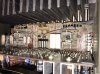
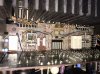
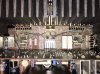
Please could you mark the resistors you’re interested in?
Hifibythekg
Super Member
The resistor that is pressed against the heat sink (right hand one above) has a little brown staining on the the thermal grease, but not sure how indicative of any damage this might be. Also don’t want to throw you off your rational deductions...

If you look at the 4 large 5 watt resistors( emitter resistors) R113,114,115,116, looks like someone changed the two on the left. They are .22ohm and should be .47ohm. If they were changed most likely at some point the output transistors may have blown. And might also be why you can not make a bias adjustment. Check the resistance of them all. if any are blown it might be the issue.
Also looks like the two smaller resisters next to the two smaller heat sinks were changed .
Id check those as well and the two transistors on those two small heat sinks.

Also looks like the two smaller resisters next to the two smaller heat sinks were changed .
Id check those as well and the two transistors on those two small heat sinks.
Hifibythekg
Super Member
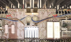
Thanks Nashou66, have I highlighted the correct components?


Circled components are the wrong value . Should be .47Ω not .22Ω like the two identical OEM resistors below them. Setting the bias per the manual is assuming .47Ω emitter resistors are installed. Have to recalculate using .22Ω emitter resistors
Which calculates out to roughly 3.4 mv target rather than 7.4 mv to get the same bias current of 15.7 ma
Last edited:
Hifibythekg
Super Member
Thanks guys.
So, MBZ, the resistors you’ve just marked all measured 4.6 ohms in circuit.
More to follow..
So, MBZ, the resistors you’ve just marked all measured 4.6 ohms in circuit.
More to follow..
Hifibythekg
Super Member
Measurements are on the photo.
I tried to measure the little white fusistors between the small heatsinks but the measurements are all over the place going up and down while the test leads are connected.
The 0.22’s.. my DMM doesn’t seem to measure accurately at this low level, but they seem to be ok, made the reading vary by 1 ohm when connected and disconnected.
I tried to measure the little white fusistors between the small heatsinks but the measurements are all over the place going up and down while the test leads are connected.
The 0.22’s.. my DMM doesn’t seem to measure accurately at this low level, but they seem to be ok, made the reading vary by 1 ohm when connected and disconnected.
Hifibythekg
Super Member
Are the 5W 0.47ohm still manufactured. Can anyone recommend the ideal replacement please?
While I’m making an order, are there any other resistors or components that I should also replace?
While I’m making an order, are there any other resistors or components that I should also replace?
Hifibythekg
Super Member
Has anyone come across the arrangement that exists on my unit? As MBZ has pointed out, there might two versions of this board. Perhaps the Japanese version doesn’t have the extra pair of resistors in the middle. (R105 and R106 pair, then R127 and R128 pair) ?
Patrice @clinic-audio might I ask whether you’ve ever come across this in your experience with this particular amp in Europe? (Mine is a UK model, 240 V.)
Patrice @clinic-audio might I ask whether you’ve ever come across this in your experience with this particular amp in Europe? (Mine is a UK model, 240 V.)
Hifibythekg
Super Member
Thanks Martin.