Hifibythekg
Super Member
Thanks... but really?
It would be such good news!
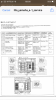
Doesn’t the service manual say
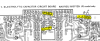
TP1 +35V, TP2 -35V
It would be such good news!
Doesn’t the service manual say
TP1 +35V, TP2 -35V



On which board ?Is TP2 actually just Ground?

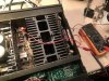
On the power circuit board, there looks like maybe an unlabelled Test Point just to the right of the VR201 trim-pot?
I do not know why the voltage ranges are +35V ± 1v and -35V ± 0.5V if there's only one test point.


TP2 on the power board is connected to 0V.Is TP2 actually just Ground?
Good news.
Audio through both speakers and green Speaker light operating. Speaker switch now serves to switch audio on speakers off and on.
Solution was applying some more Kontact40 onto the Speaker push switch and multiple workings on and off. Let’s say a hundred times.
So, to be clear, for power supply voltage one reads the contacts at 'TP' on the power board by putting one DMM lead on each of the contacts. Maybe by just swapping the leads over one then gets the two readings of +35V, then -35V.
Correct?
Nashou66, do you happen to know the part number for that Bourns that you installed, and does it work perfectly in that location.
The service manual doesn't actually mention adjusting that pot to adjust the voltage, so is it ok to do so?
Adjusting Idling Current.
Positive and negative leads applied to contacts as per the diagram in the service manual.
(Neg to TP1, Pos to TP3. Then Neg to TP2 Pos to TP4)
But I get a reading of -2.4mV, and -4.8mV. Turning up the volume increases these figures but increasingly Negative, -6mV, then -8mV.
What does this mean? Should the leads be reversed? Usually increasing the load leads to a positive rise in idling current.
Can tell that all these pots, as ever, are worn/grubby, can anyone recommend the perfect Bourns replacements?
But at least it's all working now, just want to have these currents well-adjusted and stable.
Thanks again for all the help and input so far.
Volume to be set to minimum as per SM, leave it aloneTurning up the volume increases these figures
Are you adjusting VR101,2 as per the SM, don't be overly concerned about the voltage polarity, it just means a slight shift in theincreases these figures but increasingly Negative, -6mV, then -8mV.
What does this mean? Should the leads be reversed?
I used 3296Y series, 1k ohm, you will need to bend pins to fit.can anyone recommend the perfect Bourns replacements?
Measure dc voltage at O+, black probe connected to GND, repeat for I+Question: Is the inability to change the TP1 to TP3 idle current caused by a worn or faulty trimpot, or could it be anything else?