• The move to the new server is done. There are some software and database maintenance updates in process. This has us passing the hat around to help out. We appreciate any donations. Seriously, even a dollar helps. The payment page may be found here - https://www.audiokarma.org/support.html

Yamaha A1 restoration 2021

Thanks guys but I’m still a bit confused as to how I should go about measuring this, and as the unit is working ‘fine’ at this point I don’t want to produce any magic smoke.
To put it as simply as possible, are we saying that the DMM’s red lead is placed on TP1 and the black lead on a negative speaker terminal?
Then the DMM’s red lead is placed on TP2 and the black lead on a negative speaker terminal?
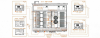
 
Thanks guys but I’m still a bit confused as to how I should go about measuring this, and as the unit is working ‘fine’ at this point I don’t want to produce any magic smoke.
To put it as simply as possible, are we saying that the DMM’s red lead is placed on TP1 and the black lead on a negative speaker terminal?
Then the DMM’s red lead is placed on TP2 and the black lead on a negative speaker terminal?

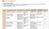
No, the black DMM lead should go to an E (earth) or chassis, red DMM lead to TP1 and then TP2 to measure the +35V and -35V ...
 
Thanks. The chassis has a black anodised coating everywhere. Does a patch need to be scraped away to ensure a secure electrical contact?
Is there anything wrong with using the negative speaker contact, only asking as at least there's some bare metal on the speaker teminal but I'm not an electrical engineer..
Also, although I'm getting sound.. the 'Speaker' button.. seems glitchy. The bulb was blown, I've replaced it with the correct bulb.. but still no light.
Depressing it on and off makes no difference to sound coming through the speakers. Doesn't seem to have the quite the same feel or action as the 'Disc' button switch. Faulty 'Speaker' switch seems to be a common problem with these units.. true?
Anyone got experience of this?
 
When I connect meter probes to chassis I look for a screw hole or similiar with some bare metal for better contact. For the A-1 you can use any black speaker post, they are connected to GND.
EDIT: Where did you get the replacement bulb for spkr button? or use a LED?
 
Last edited:
"Where did you get the replacement bulb for spkr button? or use a LED?"
Had two spare from my Yamaha CR1020 restoration. Can track down where I ordered them from if you need to know.

"Spkr button should activate a relay that connects the spkrs"
So does one only use it at startup?
 
Can track down where I ordered them from if you need to know.
Not needed. I will check the current/volt rating of the CR1020 item versus the A-1 lamp.
As I understand, you are getting audio through the speakers however the lamp is out.

So does one only use it at startup?
Select spkr button when wanting to listen through speakers. I wouldn't select spkrs when wanting to listen through headphones.
Did you measure/check the +/-35V power?
 
So this diagram by Yamaha is incorrect?
Fig 1 should be TP1 to Earth
and then TP2 to Earth
NOT TP1 and TP2 connected to the DMM?

Screenshot 2021-09-20 at 22.47.12.png
 
The A-1 lamps are speced as 14.5V 80mA. SM gives operating voltage as 12.1V
CR-1020 meter/dial lamps are 12V 60mA. I would think that they would be ok, there
is a chance of blowing due to over voltage, the A-1 guidance voltages could be
wrong. Probably just a dirty switch, needs a clean.
 
Actually I used ‘14.5V 80mA’ in the CR1020..
Cleaning the speaker switch... already put a little Kontact in there and compressed air, but does it probably require disassembly?
 
My speaker switch must be faulty if I can't switch the speakers off with it once the amp is powered on and running.
Probable

So how should I adjust Idling Current at this location?
Work through the adjustments section of the service manual.
1. First check +/-35V supply
2. Equalizer off set, you can skip this since it only applies to phono (do later)
3. MC amp distortion. Don't touch unless you have a distortion meter/analyser
4. Drive circuit DC offset
My units only have 3 pins, the middle pin is GND so check between one outer pin and GND then repeat for other outer pin and GND
5. Idle current, as per service manual
 
And on the drive circuit I can only see TP 1, TP2, TP3.
No TP 4.
View attachment 2347099
That's the "Drive Circuit Board", TP1, TP1, TP3, TP4 are on the "Electrolytic Capacitor Circuit Board"... Idling Current adjust?
index.php
 

Attachments

  • Screenshot 2021-09-20 at 17-47-55 a-1-sm-min pdf.png
    Screenshot 2021-09-20 at 17-47-55 a-1-sm-min pdf.png
    868.9 KB · Views: 138
  • Like
Reactions: mbz
Back
Top Bottom