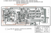
Either one of the points marked " E " on that diagram above.Where, on this particular amp, is the best place to attach the negative lead to Ground?
E = circuit ground (earth)


Either one of the points marked " E " on that diagram above.Where, on this particular amp, is the best place to attach the negative lead to Ground?
And given it’s particular design, what amperage should the mains fuse be. UK, so 240V, and options are 3A, 5A, 10A, 13A.

 Powered up and it’s working. Sounds perfectly fine on some Realistic Minimus test speakers.
Thanks MBZ.Schematic shows F203,4 as 800mA slow blow/timed. These are on the secondary windings
so should remain 800mA. For the european model a 1.6A slow blow is included on the primary.
Back panel shows 450VA at 240V gives 1.8A, I'd stick with 1.6A slow blow, round down rather than up.
View attachment 2346300 View attachment 2346300 Powered up and it’s working. Sounds perfectly fine on some Realistic Minimus test speakers.
Probably need to scrub those test points, and some Bourns trimpots would make taking readings a more satisfying procedure. When DMM readings flicker one can’t be sure if the original trimpot is unreliable.
For measuring the power supply voltage please can anyone tell me how this is done? Is it like this...?
Where is the best Ground contact on this amplifier?
- set DMM to DC volts
- Red lead to TP1 black lead to Ground?
- Then red lead to TP2 black lead to Ground.
2A should be plentyin the UK we also have a little fuse in the mains/wall plug. It’s that one I was wondering about.
I like to use any black speaker post (common GND amps), often it's a clip type, eg, CA-1000, though the A-1 uses a screwWhere is the best Ground contact on this amplifier?
You can do it as per the service manual. If you have the base off then stand amp on side, some nice test points are thenFor measuring the power supply voltage please can anyone tell me how this is done? I
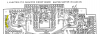
Thanks Martin but, pardon me if I’m missing something really obvious, TP1 to TP2 only gives one readout and the manual shows two.. +35, and -35..?Fig. 1 +ve to TP2 , -ve to TP1


E to TP1 and E to TP2 ... The posted manual diagram is wrong..TP1 to TP2 only gives one readout and the manual shows two.. +35, and -35..?
Correct..For measuring the power supply voltage please can anyone tell me how this is done? Is it like this...?
- set DMM to DC volts
- Red lead to TP1 black lead to Ground?
- Then red lead to TP2 black lead to Ground.
E to TP1 and E to TP2 ... The posted manual diagram is wrong..
oops, yes.E to TP1 and E to TP2 ... The posted manual diagram is wrong..