• The move to the new server is done. There are some software and database maintenance updates in process. This has us passing the hat around to help out. We appreciate any donations. Seriously, even a dollar helps. The payment page may be found here - https://www.audiokarma.org/support.html

Yamaha A1 restoration 2021

Yes, thanks Martin TP1, TP1, TP3, TP4 are on the "Electrolytic Capacitor Circuit Board"... Idling Current adjust is fine.
It's Step 4's instructions which don't match with what's available on the Drive circuit board.
Seem to have figured this out though now.
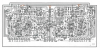
 
I think TP3 is actually an E (earth). What happens when you measure TP1 to TP3 and TP2 to TP3 ?
index.php

The Fig. 4 diagram is correct, it's showing measuring TP1 to TP3 , and TP2 to TP3 to get the idling current.

index.php
 

Attachments

  • Screenshot 2021-09-20 at 18-04-42 a-1-sm-min pdf.png
    Screenshot 2021-09-20 at 18-04-42 a-1-sm-min pdf.png
    506.9 KB · Views: 120
Last edited:
  • Like
Reactions: mbz
Thanks Martin. Will jump on to this after I’ve sorted the following problem.

At this stage, Amp initially is working ’fine’ but needs some fixing and adjustments.

So.. tried to clean out the Speaker switch with a little WD40 followed by Kontact and compressed air.

Started to get nasty loud scratch static type sounds through left speaker whenever the amp is switched on.

Finally measured Power Supply

TP 1 is 35.2V stable

TP2 is 0.05V stable. !!


Speakers will not play now.
Relays don’t trigger.

These issues have only arisen since working on the Speaker switch. Maybe I should disassemble it and either fix or replace before further testing?
 
Yes, somewhat rash I agree. But I only used a drop and very quickly followed with 'Kontakt 40' and compressed air blasts.
Could a malfunctioning Speaker button switch have the ability to cause the virtual 'no voltage' readout on TP2?
 
Yes, somewhat rash I agree. But I only used a drop and very quickly followed with 'Kontakt 40' and compressed air blasts.
Could a malfunctioning Speaker button switch have the ability to cause the virtual 'no voltage' readout on TP2?

No, the speaker switch is after the amplifier and before the outputs. And you're eventually going to need to properly clean that switch. WD stands for water displacement. It's not a switch cleaner.

Spot the difference;
1618521964-revised30055-specialist-contact-cleaner-11oz-new-look-3-8-21.png
1581008581-wd40300-x-54012.png
 
Last edited:
"These issues have only arisen since working on the Speaker switch. Maybe I should disassemble it and either fix or replace before further testing?"
Yes, I agree, it needs to be working properly.
Now also looking for any advice on what could be causing the virtual 'no voltage' readout on TP2?
 
Something bad happened. I don't know enough to hazard a guess, but time to undo the last thing you did do. Compress air may have bent something too (no idea what pressure you had).
 
My units are from the Japanese market, ie, early serial numbers. They only have the one bias TR, also TP2 is connected to GND.
OK, not real clear, meant TP2 for +/-35V power adjust.
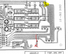
Checking the board layout confirms this, focus on the spkr switch

upload_2021-9-22_6-40-49.png
 
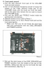
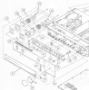
Thanks Martin, yes, I’d already followed these instructions from the manual you kindly sent. However, the face plate near to the volume pot has some extra retaining screws and clips. Hoping that someone might have previously done this removal and knows the best way to do it with the least amount of disruption and disconnections.
 
Maybe you should take some pics.
index.php
index.php
 

Attachments

  • Screenshot 2021-09-21 at 19-03-24 a-1-sm pdf.png
    Screenshot 2021-09-21 at 19-03-24 a-1-sm pdf.png
    461.5 KB · Views: 102
  • Screenshot 2021-09-21 at 19-03-56 a-1-sm pdf.png
    Screenshot 2021-09-21 at 19-03-56 a-1-sm pdf.png
    374.9 KB · Views: 99
Thanks Martin.
Now sorted.
The volume pot was more adhered to the face plate than was helpful. Prised it off, and now on to the next phase..
 
Have tested power supply voltages at TP1 and TP2.

Bad news is that TP2 reads 0 V.

TP1 to Ground reads -35.1V
TP2 to Ground reads 0.0V

Sound only through the left speaker.

Power switch light now doesn’t light up, it used to.

Have disassembled the speaker relay (in the transparent plastic box) and carefully cleaned what had been very tarnished contacts.

How do I go about checking out the cause of no power to TP2?

Some additional info, don't know whether this might this help diagnosis..?

When the unit is powered OFF:

- TP1 to Ground, chassis Diode test function on DMM reads 1248 and no beep.
Also, when this reading is taken the reading starts at about 800 and takes about 5 seconds to climb to climb to 1248.

- TP2 to Ground, chassis Diode test function on DMM reads zero and beeps

- TP1 to Ground has resistance of 9-ish Kohms but this can vary and climbs or descends over a few minutes.
- TP2 to Ground has 0.1 ohm resistance

TP1 is the contact located nearer the centre of the board, it’s not actually labelled on the board itself.
 
...also.

Disc button works operates well and lights up.

Speaker button will work and let music play through the left speaker. But it doesn't switch the sound off and on after this initial functioning.
Spekaer button doesn't light up.
Power button button doesn't light up.
Both used to (bulb in Speaker button is correct type, tested, and newly installed.)
 
The right side is clearly not working. All I can surmise is that WD40 in the speaker switch caused a dead short for the right side or something else similarly bad. Not good.
 
Thanks Martin.
I checked the speaker switch with the DMM and it seems to be working well. It’s a knitter-switch I believe, does anyone know exactly which model I should order for replacement?
 
Back
Top Bottom