• The move to the new server is done. There are some software and database maintenance updates in process. This has us passing the hat around to help out. We appreciate any donations. Seriously, even a dollar helps. The payment page may be found here - https://www.audiokarma.org/support.html

Zilch's AK Design Collaborative - Econowave Speaker

...that anyone with a monitor less than room size wanted to actually see all of Newman's CL score above, I offer a tweaked & reduced version of the original posting. :tongue:

PB010011.JPG

Dave, did you really aquire this stuff or is that just some good natured kidding going on? If so, Holy Cow!

russellc
 
Oh my. No, I just found the pics in another thread.

I did acquire some speakers on CL recently, but nothing quite that crazy. I am disappointed that I hesitated on some JBL 2360As recently and missed out.
 
Oh my. No, I just found the pics in another thread.

I did acquire some speakers on CL recently, but nothing quite that crazy. I am disappointed that I hesitated on some JBL 2360As recently and missed out.

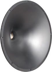
The 2360A is the horn in the pic on top of the dual driver boxes? guys on the LHF are using those giant speakers in living rooms, allegly with excellent results in all but the WAF dept.:D

russellc
 
A little bit of "layman's" term for charge coupling, caps are said to not sound as good
without having some DC present on them, so the charge coupling supplies a DC "bias"
to the caps that otherwise they would have no dc on them and therefore are said to
sound better in this regard with having the dc present at all times.

That's the theory anyway, I haven't tried it, but I am inclined to believe that there is
something to it with other experiences with caps and varying voltages.
 
The 2360A is the horn in the pic on top of the dual driver boxes? guys on the LHF are using those giant speakers in living rooms, allegly with excellent results in all but the WAF dept.:D

russellc

Correct, 2360 and 2360A are the two variants of that horn. They are reportedly quite good, but I've never actually heard them. I showed my wife and she seemed ok with them the first time. The second time I showed her a pic, she only responded with laughter.
 
A little bit of "layman's" term for charge coupling, caps are said to not sound as good
without having some DC present on them, so the charge coupling supplies a DC "bias"
to the caps that otherwise they would have no dc on them and therefore are said to
sound better in this regard with having the dc present at all times.

That's the theory anyway, I haven't tried it, but I am inclined to believe that there is
something to it with other experiences with caps and varying voltages.

Do you think the "increased clarity" would be a good or bad thing for the Selenium driver in particular? I sort of think its "pleasant breakup" could get uglier. If the breakup is somehow reduced by CC, might it reduce the very high frequency response, since it is somewhat enhanced by the breakup modes?

russellc
 
The breakup modes are in the driver/diaphragm it'self, if there there they will always be
there, so the high frequency won't reduce because of it, could it get "uglier" soundwise
by "increased clarity", yah I would say the possibility is there. Won't know till yu try...:)
 
OK guys I am starting a new project and here is what I have. A pair of American Monitor 10s with fried egg tweets (I think from CTC) and 10" woofs with rotted foam. I have the Eminence ASD 1001 which I can't get the plot to copy here but you can see it on the link. and the round Parts Express 12" waveguide. The cabs are VERY solid. Here are some pics below. So 1. what woofer do your think that is?, 2. what crossover should I use, 3. how does that compression drive look as a fit for an ewave? Cheers.

IMG_3261.jpg


IMG_3266.jpg


270-312m.jpg
 
Last edited:
The networks employ DC bias to operate the capacitors effectively in a Class A mode. The batteries provide a voltage bias to each of the capacitor positions in the various networks. The biasing of the capacitors is done through a large value resistor (2.2 megohms) and thus draws no appreciable current. The expiration date printed on the battey generally coincides with the need to replace the batteries. Each capacitor position is actually made up of two capacitors connected in series. The battery voltage is applied to the center connection of the two capacitors. This produces a voltage potential between the two plates within the capacitor. When the two parts are taken as a whole, there is no DC voltage that appears across them, but individually they are each biased. The sonic result of the biasing yields an increase in detail, increased smoothness, and considerably more natural decay of sounds within the music.

http://www.audioheritage.org/vbulletin/showthread.php?t=24086


attachment.php

http://www.audiokarma.org/forums/showthread.php?p=2018265&#post2018265
 
Sure do B. I'll give you a call this weekend. How is progress on your now ewave project?

I've wasted vast time speculating on different combinations of midranges and woofers to make a 3-way system. Nothing concrete decided yet. I'm resisting the idea of vintage woofers but that might have to be the way I go. At any rate it will take a while to accumulate all of the parts without spending a fortune. Woj was over yesterday and made off with my LS3/5As, which I suspect he won't like.
I'm listening to a pair of Frankenspeakers I made up out of some Infinity cabs and the parts from a waterlogged pair of B&W DM10's (~$500). These are some stupendous sounding 8" midwoofers, and the tweeters aren't far behind. Really outstanding sound. When I get another pair of waveguides & compression drivers in hand I'll have to try a thrown-together 2-way with these. I'm expecting magic.
I keep a lot of speaker surrounds on hand, so drop me a line before you buy anything & pay shipping.
 
This effectively puts a 9V 'bias' on the dielectrics of the caps, ensuring that when the signal passes through the zero point the capacitor does not charge and discharge its dielectric. Or that's what I'm speculating happens. Theoretically this should make no difference at all, but in a capacitor with a lot of hysterisis in the dielectric it might.

I am not an expert on electrical circuits, but the idea of a charge coupled circuit makes no sense to me...

Here's why I say this:

If you apply a 9V charge to one end of a 1.5MOhm resistor, what voltage do you have at the other end of the 1.5MOhm resistor that has near zero resistance to the negative side of the battery? I would think it is significantly less than 1/10 volt. As the AC music signal passes through this area, you mave raised the zero level by 1/10 Volt, but it still passes through a zero point because the AC voltage is higher than the <1/10 volt charge..

Does this make sense to the more knowledgable?
 
I'd have to measure to say for sure, BUT, since the caps block DC there should be no
current flowing through the 1.5m resistor there for no voltage drop and whatever the
voltage of the battery is will be on the caps. :)
 
I am not an expert on electrical circuits, but the idea of a charge coupled circuit makes no sense to me...

I'm no expert either, but you can read why Greg Timbers thought it made sense:

http://www.lansingheritage.org/images/jbl/specs/home-speakers/1993-k2-s5500/page10.jpg

http://www.lansingheritage.org/images/jbl/specs/home-speakers/1993-k2-s5500/page11.jpg

http://www.lansingheritage.org/images/jbl/specs/home-speakers/1993-k2-s5500/page12.jpg

EDIT: OH! and thanks for the offer to share speaker parts etc. I'll be in touch!
 
If you apply a 9V charge to one end of a 1.5MOhm resistor, what voltage do you have at the other end of the 1.5MOhm resistor that has near zero resistance to the negative side of the battery? I would think it is significantly less than 1/10 volt.
It's a capacitor, not a resistor, and it charges up to the applied voltage. The other ends of both caps have low-impedance paths to common with the battery. Thus, the tie point between the two caps sits at 9V rather than 0V, and is modulated by the AC signal passing through. You have to be applying an 18V P-P AC signal to drive it down to the capacitor's zero voltage crossing, which is mighty damn loud. It's DC bias and can't flow out of the caps, the only drain being leakage, which is constantly refreshed by the 1.5 or 2.2 meg resistor.

[I showed this on an oscilloscope over in LHF for the inquisitive and resourceful researchers among us.... ;) ]
 
I'd have to measure to say for sure, BUT, since the caps block DC there should be no
current flowing through the 1.5m resistor there for no voltage drop and whatever the
voltage of the battery is will be on the caps. :)

Not trying to be argumentative, but if that is the case, why do you need a resistor in the first place?
 
Not trying to be argumentative, but if that is the case, why do you need a resistor in the first place?
If the resistor weren't there, the battery would be a low impedance path to common, a 9V short, effectively, and the operating point would never modulate to pass the signal through.
 
Probably to protect the battery in case of a short, or the speakers in case a cap goes
to leaky or just becomes unstable for whatever reason.


---------

Edit, Yah what he said... :)
 
Back
Top Bottom