

You are using an out of date browser. It may not display this or other websites correctly.
You should upgrade or use an alternative browser.
You should upgrade or use an alternative browser.
Zilch's AK Design Collaborative - Econowave Speaker
- Thread starter Zilch
- Start date


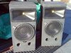
A sneak picture of the AWA Video 1 rear E-wave speakers:

This room is going to sound GOOD. :thmbsp:
Now, to consider upgrading the Marantz SR4400... just got a SR7400 (105w/ch as opposed to 80w/ch for the SR4400)... that, plus the Carvin HD1800 running left and right mains (the Marantz, which ever one winds up being used, only runs center and rears through its own amp), and the twin BASH 300 watt amps on the subs... I think it oughtta have enough dynamic range.
Regards,
Gordon.
This room is going to sound GOOD. :thmbsp:
Now, to consider upgrading the Marantz SR4400... just got a SR7400 (105w/ch as opposed to 80w/ch for the SR4400)... that, plus the Carvin HD1800 running left and right mains (the Marantz, which ever one winds up being used, only runs center and rears through its own amp), and the twin BASH 300 watt amps on the subs... I think it oughtta have enough dynamic range.
Regards,
Gordon.
Attachments

From five minutes playing in Win ISD, I'd say 3 ft^3 is a bit too big for the 3012LF. Look at 2 ft^3 / 35 Hz vs. 3 ft^3/ 35 Hz. The smaller box loses a only touch of output around 40 Hz, but has better power handling, lower excursion for any given power input, lower port velocity (given equal sized ports) and lower group delay within the passband. Plus a smaller cabinet (all things being equal) will have stiffer walls, take less material and be lighter to move around.
Bill
I think Bill has a point here. If you're already resigned to using a subwoofer, the smaller cabinet may be to your advantage. I've seen some pretty impressive results with this sort of cabinet alignment- Dan Wiggins, formerly of Adire Audio, posted quite a bit of results with slightly-smaller-than-normal vented enclosures, tuned slightly-lower-than-normal in frequency. He also found good transient response...
Also, this would result in a response curve, that even more closely matched what Wayne was describing- more like a "sealed box response"... but with the additional power handling and reduction of distortion (due to lowered excursion in the lowest frequencies) due to the vent...
Regards,
Gordon.

Russellc
Addicted Member
That is all looking very nice. It'll be interesting to see where the inverse vertical null actually falls, indicating the true forward axis.
Were there any eWaves at AK Fest?
[Post a pic showing both cabs, and we can make you "Official"...." :thmbsp: ]
Zilch, I have a question. I have read and reread several of your posts concerning the "inverse null" and how it indicates the "true forward axis". This just isnt gelling in my mind, I assume that others may have difficulty with this as well. Could you dumb this down a bit so I could understand this? It seems like a terribly important part of E'wave design. If I'm wrong and I'm the only dummy, we can do this by PM. I dont mind sharing my ignorance on the world wide web if it will help spread the info. I am failing to understand how the null indicates the forward axis. I understand that if one of the drivers polarity is reversed, one can measure the inverse null, what I cant fathom is how the forward axis is indicated by this. Maybe my uinderstanding of forward axis is wrong, maybe we could start there.
Sorry to wait this far into the program, I thought it woul;d eventually come to me, but thus far that hasnt happened. Seems like it will be awfully important to understand this for my upcoming E'wave undertakings, and design in general. Am I the only one having difficulty with this?:scratch2:
Thanks for the trouble,
Russellc

donprice
Wound up workin' at a gas station....
I am failing to understand how the null indicates the forward axis. I understand that if one of the drivers polarity is reversed, one can measure the inverse null, what I cant fathom is how the forward axis is indicated by this. Maybe my uinderstanding of forward axis is wrong, maybe we could start there.
Think wave superposition. For the same frequency (like at the crossover) - in-phase = additive, out of phase = cancellation. It is easier to spot the inverse null (due to cancellation) than to spot a maximum (due to the logrithmic nature of SPL?). I think that is how it works.
Look for a post (~page 500?) linking to a Wayne Parham video showing him hunting for the elusive null using a laptop and microphone.

The plots look quite nice, Markus, and the box looks good as well.
How did you measure the system response (red) all the way down through the lows?
Curious to see how measured polars reflect your sims. And did you use Soundeasy for your x-o design?
:thmbsp:
The red line is not valid below the shaded area. The program just fills in the projected response, which is not correct.
I'll be very curious to see how the polars reflect the sims as well. I think the waveguide measurements were very good, but the woofer measurement was colored by floor bounce. This could through things off.
I am using soundeasy for the xover design.
Markus
Looking good Marcus. Sorry I did not get a chance to talk with you at the fest. Seems like every time we saw each other we were going in opposite directions. Do you have Lpads in the crossover?
Me too Denis. It seemed like I was running around all over the place the whole weekend. What a blast! We'll have to catch up at one of the smac meets. I'm hoping my work schedule lets up a bit and I can stop working Saturdays.
Yes, I put L-pads in the crossover, at least to start. I may replace them with fixed resistors when the design settles down, but maybe not. l-pads are nice to have sometimes.
Markus

Through the crossover region, both woofer and waveguide are playing the same frequencies. That's two sources with the same program, and they add to and/or interfere with each other to varying degrees depending upon the relative distance of the listener (or measurement microphone) from each of them. When the distance to each is the same, and both are in phase, they sum maximally, and conversely, when they are out of phase, they cancel maximally. We design such that the listener listens from where the two sources are in-phase and summing maximally.
The listener and the two sources in a single speaker, the woofer and waveguide, form an imaginary triangle in the vertical plane (on-axis horizontally) when they are mounted one above the other. When the distance of the listener to the acoustic center of each of them is the same, that triangle is isosceles, and the summation is maximal. Viewed from the side, it is easily seen that, as the listener moves up and down from the point midway between the drivers one side of that triangle (representing the distance of the source to the listener) becomes longer, while the other becomes shorter, the distances are no longer identical, and the summation is less perfect. In waveguide speakers, the vertical distance between the sources themselves (the base of the imaginary triangle) is large, and small movements of the listener (or microphone) up or down at typical listening distances create large differences in the relative distance to each of the sources.
What we call the "forward vertical axis" of the speaker the line between the apex of that triangle and the midpoint between the acoustic centers of the two sources vertically, the midpoint of the base of the triangle, when the two sides of that triangle, representing the distances from each source to the listener, are equal, and the summation, maximal.
While it is possible to determine the exact location of the acoustic centers of the two sources via measurements, it may be easily seen that, if the upper one is displaced further back than the lower one, as is typically the case with a woofer and waveguide, the triangle "points" upward from the midpoint between them. With a typical woofer and tweeter, the situation is opposite, with the woofer being behind, and the triangle pointing downward. In both cases, we can manipulate the virtual locations of the acoustic centers via delay, either actual or phase delay, or both, to "aim" the triangle wherever we want, typically such that the apex of the imaginary triangle, the forward vertical axis, "points" toward the listening height of the listener.
For any given system under design and measurement, how might we easily determine the actual alignment and get it "right?" The determination part is easy, actually: if we invert the polarity of one driver or the other, instead of maximally summing at the apex of the triangle, the forward axis, the drivers maximally cancel there, and a deep notch appears in the amplitude response measurement of the system at the acoustic crossover frequency. By moving the microphone up and down and taking repeated measurements, we can locate exactly where that notch is deepest (the cancellation being maximal) within 1/2 the diameter of the microphone aperture, typical, ~1/8". Knowing the height of the microphone relative to the midpoint between the drivers and the horizontal measuring distance, we can calculate the displacement angle of the forward axis relative to normal (perpendicular to the baffle) in pursuit of our design target.
Cool, huh?
The listener and the two sources in a single speaker, the woofer and waveguide, form an imaginary triangle in the vertical plane (on-axis horizontally) when they are mounted one above the other. When the distance of the listener to the acoustic center of each of them is the same, that triangle is isosceles, and the summation is maximal. Viewed from the side, it is easily seen that, as the listener moves up and down from the point midway between the drivers one side of that triangle (representing the distance of the source to the listener) becomes longer, while the other becomes shorter, the distances are no longer identical, and the summation is less perfect. In waveguide speakers, the vertical distance between the sources themselves (the base of the imaginary triangle) is large, and small movements of the listener (or microphone) up or down at typical listening distances create large differences in the relative distance to each of the sources.
What we call the "forward vertical axis" of the speaker the line between the apex of that triangle and the midpoint between the acoustic centers of the two sources vertically, the midpoint of the base of the triangle, when the two sides of that triangle, representing the distances from each source to the listener, are equal, and the summation, maximal.
While it is possible to determine the exact location of the acoustic centers of the two sources via measurements, it may be easily seen that, if the upper one is displaced further back than the lower one, as is typically the case with a woofer and waveguide, the triangle "points" upward from the midpoint between them. With a typical woofer and tweeter, the situation is opposite, with the woofer being behind, and the triangle pointing downward. In both cases, we can manipulate the virtual locations of the acoustic centers via delay, either actual or phase delay, or both, to "aim" the triangle wherever we want, typically such that the apex of the imaginary triangle, the forward vertical axis, "points" toward the listening height of the listener.
For any given system under design and measurement, how might we easily determine the actual alignment and get it "right?" The determination part is easy, actually: if we invert the polarity of one driver or the other, instead of maximally summing at the apex of the triangle, the forward axis, the drivers maximally cancel there, and a deep notch appears in the amplitude response measurement of the system at the acoustic crossover frequency. By moving the microphone up and down and taking repeated measurements, we can locate exactly where that notch is deepest (the cancellation being maximal) within 1/2 the diameter of the microphone aperture, typical, ~1/8". Knowing the height of the microphone relative to the midpoint between the drivers and the horizontal measuring distance, we can calculate the displacement angle of the forward axis relative to normal (perpendicular to the baffle) in pursuit of our design target.
Cool, huh?
Last edited:

Spasticteapot
Nuclear Liberal
I have a budget of approximately $300 to build some Econo-Waveguides. These will be used as PA speakers (though only in very small rooms - the sort of things people use those rubbishy little Bose PA speakers for), and need to be able to produce some fairly impressive SPL. Can anyone recommend a woofer/xover to me? Or perhaps sell me some parts?
EDIT:
Has anyone considered either a 3.5-way or MTM configuration using two DC300s? It seems a shame to spend more on your xover than you are on your woofers.
EDIT:
Has anyone considered either a 3.5-way or MTM configuration using two DC300s? It seems a shame to spend more on your xover than you are on your woofers.
Last edited:
Building your own cabs?I have a budget of approximately $300 to build some Econo-Waveguides. These will be used as PA speakers (though only in very small rooms - the sort of things people use those rubbishy little Bose PA speakers for), and need to be able to produce some fairly impressive SPL. Can anyone recommend a woofer/xover to me? Or perhaps sell me some parts?
Slam dunk done:
http://www.audiokarma.org/forums/showthread.php?p=3383067#post3383067
http://techtalk.parts-express.com/showthread.php?p=1643004#post1643004
Last edited:
Spasticteapot
Nuclear Liberal
Building your own cabs?
Slam dunk done:
http://www.audiokarma.org/forums/showthread.php?p=3383067#post3383067
http://techtalk.parts-express.com/showthread.php?p=1643004#post1643004
I'm a bit perplexed - the CLIO measurement shows -10dB at 50hz.
I'm not brilliant at Xover design, but it does seem that adding a second woofer in parallel with a 6dB low-pass at about 160hz would help prop up low-end response a bit without requiring to much excursion. Or am I reading this wrong?
Now that AK Fest is over :tears: I made a little progress on the JBL 123 Delux ewaves.
Markus
Looking good, Markus. I'll give your crossover a try. Thanks - Pat
If you're building your own cabs, you can go ahead and make them around 3 cubic feet. That volume has been tested extensively, to work well with the DC300 12" woofer. Solid bass to down to 30 Hz or so. Tune the cabinet between 25 and 27 Hz, to taste.
Regards,
Gordon.
Regards,
Gordon.
Dave is correct. Low frequency response is not shown; it must be measured using other means.
See the legend of the CLIO plots - the frequency resolution based upon the gating time is indicated there. It's a limitation of quasi-anechoic measurement methodology; accuracy diminishes as resolution decreases. Under these conditions, anything below 1 kHz is increasingly dubious.
Most all low frequency response measurements you see published are synthesized to one degree or another. There are no anechoic chambers (other than outdoors) large enough to accurately resolve 20 Hz, even. We therefore approximate the low frequency response using techniques such as nearfield and groundplane.
Read up here:
http://www.stereophile.com/reference/105kh/index.html
See the legend of the CLIO plots - the frequency resolution based upon the gating time is indicated there. It's a limitation of quasi-anechoic measurement methodology; accuracy diminishes as resolution decreases. Under these conditions, anything below 1 kHz is increasingly dubious.
Most all low frequency response measurements you see published are synthesized to one degree or another. There are no anechoic chambers (other than outdoors) large enough to accurately resolve 20 Hz, even. We therefore approximate the low frequency response using techniques such as nearfield and groundplane.
Read up here:
http://www.stereophile.com/reference/105kh/index.html

Navydoc
New Member
From five minutes playing in Win ISD, I'd say 3 ft^3 is a bit too big for the 3012LF. Look at 2 ft^3 / 35 Hz vs. 3 ft^3/ 35 Hz. The smaller box loses a only touch of output around 40 Hz, but has better power handling, lower excursion for any given power input, lower port velocity (given equal sized ports) and lower group delay within the passband. Plus a smaller cabinet (all things being equal) will have stiffer walls, take less material and be lighter to move around.
Bill
I think Bill has a point here. If you're already resigned to using a subwoofer, the smaller cabinet may be to your advantage. I've seen some pretty impressive results with this sort of cabinet alignment- Dan Wiggins, formerly of Adire Audio, posted quite a bit of results with slightly-smaller-than-normal vented enclosures, tuned slightly-lower-than-normal in frequency. He also found good transient response...
Also, this would result in a response curve, that even more closely matched what Wayne was describing- more like a "sealed box response"... but with the additional power handling and reduction of distortion (due to lowered excursion in the lowest frequencies) due to the vent...
Regards,
Gordon.
Thanks for the input...I will make the cabinet smaller (keeping the same 17" baffle width of the PE Trap that used for XO optimization).
I plan on extensive bracing with 1.5" x 1.5" poplar - doesn't cost much, makes it easier to keep the panels square during construction, and will take up internal space to lower the cabinet volume.:thmbsp:
donprice
Wound up workin' at a gas station....
I have a budget of approximately $300 to build some Econo-Waveguides. These will be used as PA speakers (though only in very small rooms - the sort of things people use those rubbishy little Bose PA speakers for), and need to be able to produce some fairly impressive SPL. Can anyone recommend a woofer/xover to me? Or perhaps sell me some parts?
Are you going to be running a sub? If so, you can look at some of the higher efficiency pro audio woofers though most of them bust your budget. Just looking at the specs/curves, the $65 Eminence Beta 12A and the JBL LE14 version of the eWave crossover just might work out nicely. Not much risk if you have a 1/3 octave EQ in the rack to smooth out the crossover region (if needed).
Spasticteapot
Nuclear Liberal
Are you going to be running a sub? If so, you can look at some of the higher efficiency pro audio woofers though most of them bust your budget. Just looking at the specs/curves, the $65 Eminence Beta 12A and the JBL LE14 version of the eWave crossover just might work out nicely. Not much risk if you have a 1/3 octave EQ in the rack to smooth out the crossover region (if needed).
Sadly not - there's simply no budget for it. I have a sneaking suspicion that while the speakers can easily make the 50hz f3 I'm looking for, they'll be excursion-limited to far less output than I want. A second woofer adds only a bit more to the cost, but allows for +6dB output - and that makes a difference.