• The move to the new server is done. There are some software and database maintenance updates in process. This has us passing the hat around to help out. We appreciate any donations. Seriously, even a dollar helps. The payment page may be found here - https://www.audiokarma.org/support.html

Zilch's AK Design Collaborative - Econowave Speaker

Here is my baffle board with proposed layout. I would like to know if there is an "optimal" placement of the driver and horn other than what I've randomly selected. Also, the inside volume of the cabs are 5.75 cu/ft. There is a port built into the bottom of the cab that is 16" wide, 2" high and 11 inches long. Will I need to block this off and put in different ports or will the built in one work for this application?

Arg! I was so close to getting a free pair of Heathkit speakers with those woofers that I was going to E-wave. You beat me too it. Totally envious.
 
Here is my baffle board with proposed layout. I would like to know if there is an "optimal" placement of the driver and horn other than what I've randomly selected. Also, the inside volume of the cabs are 5.75 cu/ft. There is a port built into the bottom of the cab that is 16" wide, 2" high and 11 inches long. Will I need to block this off and put in different ports or will the built in one work for this application?
Looking good. Those are of similar construction to Barzilay cabinets that I'm using. Are you going to add any additional bracing? I'm in the process (almost finished) of adding additional bracing to my cabinets. The link to mine is in my signature. I'm adding battens on the top and sides and a window brace that will tie the four sides and top together. Additional bracing has been added to the bottom and a thicker rear panel was created. I'll be working on mine again this afternoon and will post a few photos of what I have so far.
 
I have started my advent Ewaves with my first ever crossover build and had a great time doing it not as hard as I thought it would be.I used the old rear panel from the speakers to mount the Lpad and some JBL L20T binding posts I have recently purchased turned out OK.I have a question how do I use that fuse protection circuit or do I need one.Heres some pictures.Thanks Zilch for all the info.Will add more pictures as I move along.:D

I installed a 3A fuse in the first pair of Advents I Ewaved. I had just rebuilt the guy's Phase Linear 700B and he's half deaf. Figured the speakers needed a fighting chance. It's not necessary for sane people with reasonable expectations.
 
Be sure to compliment me on my cabinet work

I tried to test out my driver plan today with drivers mounted on a cardboard box (using the box from the PE trap cabinet in fact- what are all those wood things inside for, BTW? :D). For crossover, I just tack-soldered together the components for the basic eWave crossover for <95dB SPL (looks like I should have used the one for >95, though, ran out of gas on the L-pad).

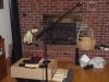
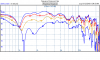
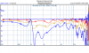
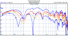
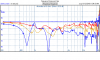
I wanted to do outdoor measurements, but showers are predicted for all day today. So, the family room it is. I put a thin wire from one of the waveguide mounting holes to the mic clamp and used it so all measurements are 1 meter from that point, and eyeballed the angles. The "dBr" values shown are the correct dBSPL sensitivities for 2.83V. See the photo for the meticulous lab setup.

The results are of dubious value, IMO, but here they are for anyone who wants to try interpreting. I think the floppy cardboard box, with unsealed holes even, is resonating like mad, particularly around 1kHz (unfortunately right around where I'm most interested). So the directivity plots aren't great.

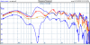
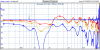
First two plots are with the drivers all flush mounted, horizontals (0, 22, 45, 67 degrees), then as if equalized to flat on-axis; next two are verticals (0, 12, 22, 45 degrees).

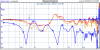
(In a post to follow, because of limited uploads allowed --) Third two are with the waveguide pulled forward about 3inches to roughly align the voicecoils. Horizontals; Horizontals as if eqd; Verticals; Verticals as if eqd/

No smoothing applied to any of the curves, windowing is set so that anything below about 700Hz is dubious. If you squint your eyes (and maybe wish a little), you can see the directivity working below the crossover points from the 4 woofers. To get around the boxy wall resonances, I'll probably have to commit to wood and bracing. I think I'll want to go outside, too, for measurements, since 1 meter isn't much distance for vertical measurements on drivers that span over 18 inches.

Here they are:

 

Attachments

  • Setup.jpg
    Setup.jpg
    26.5 KB · Views: 59
  • horizontals 0 22 45 67.PNG
    horizontals 0 22 45 67.PNG
    25 KB · Views: 32
  • horizontals 0 22 45 67 Norm.PNG
    horizontals 0 22 45 67 Norm.PNG
    23.6 KB · Views: 25
  • verticals 0 12 22 45.PNG
    verticals 0 12 22 45.PNG
    19 KB · Views: 25
  • verticals 0 12 22 45 Norm.PNG
    verticals 0 12 22 45 Norm.PNG
    23.6 KB · Views: 22
Last edited:
Here's the plots with the guide pulled forward

I also tried playing with the polarities on the drivers, but those didn't make things better. I'll clearly need to do crossover work no matter how I go, unless the box resonances is causing all the grief around 1-2kHz.
 

Attachments

  • Horizontal.PNG
    Horizontal.PNG
    17.1 KB · Views: 14
  • Horizontal Norm.PNG
    Horizontal Norm.PNG
    15.6 KB · Views: 14
  • Vertical 0 12 22 45.PNG
    Vertical 0 12 22 45.PNG
    18.1 KB · Views: 14
  • Vertical  Norm 0 12 22 45.PNG
    Vertical Norm 0 12 22 45.PNG
    16.3 KB · Views: 15
Maybe your 67º horizontal null at about 1.2-1.5k is proving your concept.
Woofer directivity narrowed. Would be interesting to see what happens to that null at 90º.

So is it enough evidence for you to cut wood?
 
I would be expecting to see nulls in the horizontal as well as the vertical with pairs of woofers in both directions.... :yes:
 
I would be expecting to see nulls in the horizontal as well as the vertical with pairs of woofers in both directions.... :yes:

Even with the woofers mounted adjacently? I was thinking that would act more or less like a single driver, at least below the crossover point here.

I think part of the problem, at least here, is that I have an extra emitter in the form of the cardboard box. Even the directivity up where only the guide is getting driven looks pretty erratic.

So, not enough evidence to cut wood really, but probably won't be any better evidence until I do.
 
Barziwave question

I have a pair of Barzilay cabs..is there any clearance issue with the Ewave horn
in relation to the baffle and grill ? :scratch2:
 
I have a pair of Barzilay cabs..is there any clearance issue with the Ewave horn
in relation to the baffle and grill ? :scratch2:

Unlikely. I think the depth requirement is around 5.5" - 6.5" with the PH612/D220TI setup. The QSC rectangular with B&C driver is about 7" clearance.

Oh, I thought you meant behind the baffle. The waveguide should be surface mounted or flush mounted, so the only clearance issues there are with surface mounted grilles where the existing drivers were back mounted.
 
Unlikely. I think the depth requirement is around 5.5" - 6.5" with the PH612/D220TI setup. The QSC rectangular with B&C driver is about 7" clearance.

Oh, I thought you meant behind the baffle. The waveguide should be surface mounted or flush mounted, so the only clearance issues there are with surface mounted grilles where the existing drivers were back mounted.
That's the question and I didn't want to go through Similosts whole thread to find the answer.
I know duffinator built some. I was hoping someone that has built them would chime in. :yes:
 
Horizontal nulls

I covered the lower set of woofs with books (handy acoustical and mechanical spacing tools) and looked at the horizontal nulls from just two woofers. Some is definitely coming from the box, as I can see get circumstances where the level doesn't even drop as I go to far horizontal angles.
But the two remaining discrete drivers are having an effect, too, like Zilch said. I cut the cardboard and moved the two woofers right along side each other and the nulls moved upward to where the crossover and the waveguide pretty much hides them (added holes and different loading on cardboard probably having an effect too, though). So, for the horizontals, I'd say the two woofs clearly should be pushed right next to each other to make for the best horizontal pattern. I'm not sure about whether the vertical pattern is best served by having woofs above and below or just all of them clustered below; the crude spreadsheet model says 2MTM2 should be better, but the cardboard model doesn't show anything very clearly....
 
Duff I was considering adding bracing but not really sure what the proper process is for doing so, and just how far you need to take it. I'm very interested in seeing pics of your bracing. I should be ready to install the baffle assy's into the cabs by the time they get back from the finisher so I'm sure I'll try them initially as is. This project has been a long time coming to completion so I Know I won't be able to resist giving them a test drive first.
 
Optimal is with the woofer and waveguide snugged up to each other and located near the top of the baffle, much as you have shown.

BB6P says that port will have them tuned to 32.57 Hz. You're good to go.... :thmbsp:

So is this pretty much around optimum or can I make adjustments to the port to make it go lower?
 
Oooops, I'm sorry Zilch I screwed up. Interior volume is 7.5 cu/ft not 5.75 cu/ft. Where does that put me at? Box dimensions are 30 high by 24 wide by 18 deep.
 
Back
Top Bottom