• The move to the new server is done. There are some software and database maintenance updates in process. This has us passing the hat around to help out. We appreciate any donations. Seriously, even a dollar helps. The payment page may be found here - https://www.audiokarma.org/support.html

Zilch's AK Design Collaborative - Econowave Speaker

Here are the files if anyone wants to try their hand with it in PCD. C/C distance is 13", measurement distance 44" from midway between woofer and waveguide, and HF z offset = -79 mm, i.e., 3.11" behind the woofer acoustic center:
 

Attachments

Last edited:
Zilch, your timing is amazing. The photos below are what I have accomplished while waiting for the new foam edges to come in and the crossover design you used. Used Howards on the veneer, painted the bottoms (now the top), put on some legs, and attached the waveguides using the old riser on the bottom and a couple of decorative shelf brackets.
IMG_0202.jpg
 
I realy like those cabs JB. Very cool legs.

Hi All, here is a screen shot of "the EDGE" program used to sim Open Baffle Line Arrays. I've got it so it is flat betweet 150hz and 1khz.

On the left side you can see the layout of the baffle board. The gap in the middle is were the 6x6 JBL wave guide will go.

My question is this: the responce looks to be about 3db down at 1.5khz or so and is that "OK" for crossing to the 6x6 jbl WG?

OpenBaffleLineArrayeWave.jpg
 
1st speaker build- E-wave Jensen Spectrum 540's?

This has been an amazing post to browse thru. Thanks to zilch and everyone that have done so much work to make it easy for the rest of us to build great speakers that are affordable!

I have a set of Jensen Spectrum 540's that sound only so-so, but look fantastic. 12" woofers so a perfect candidate.

I am using a Maganvox 9302 tube amp in a small room so i want efficient to go with outstanding sound.

Can I use the Dayton Pro 12's.
*VCdia: 3" *Le: 1.53 mH *Impedance: 8 ohms *Re: 5.7 ohms *Frequency response: 44-4,000 Hz *Fs: 44.4 Hz *SPL: 97.2 dB 2.83V/1m *Vas: 2.89 cu. ft. *Qms: 8.63 *Qes: 0.34 *Qts: 0.32 *Xmax: 5.0 mm
http://www.parts-express.com/pe/showdetl.cfm?Partnumber=295-032

with the base econo wave x-over and compression driver?

Cabinet measures at 2.2 cu ft (62.3liters) not accounting for drivers.
Ported or sealed?
Would there be any downside to mounting the waveguides in the cabinet?

Thanks for any and all advice!

Pics-
picture.php


picture.php
 
You can certainly use the Pro 12s. I am looking at these for my next build. I do not believe that anyone has used these in an EWave yet. Their response is very smooth is the crossover region, but they can't tolerate a lot of power ported before exceeding Xmax. They also will not play really low. You will definitely need to port your cabs to get the lowest response. Sealed in cabs of your size, you will get an F3 of 45Hz. Ported w/ a 3x8 port you have F3 32Hz, but you are at Xmax w/ 20Watts, 103dB.

The beauty of the original XO is that it is a "module". All of the later work is to optimize with specific drivers. That work is a natural evolution of the EWave concept. However, do not let the optimization efforts obscure the fact that the original concept sounds extremely good.

You definitely want the waveguide in the cab. Minimum distance between the waveguide and the woofer is preferred.

Since the PA312 can't take much power without exceeding Xmax, I think you may as well think about the DC300. It will play much lower for the same constraints and is much cheaper.

Can I use the Dayton Pro 12's.
*VCdia: 3" *Le: 1.53 mH *Impedance: 8 ohms *Re: 5.7 ohms *Frequency response: 44-4,000 Hz *Fs: 44.4 Hz *SPL: 97.2 dB 2.83V/1m *Vas: 2.89 cu. ft. *Qms: 8.63 *Qes: 0.34 *Qts: 0.32 *Xmax: 5.0 mm
http://www.parts-express.com/pe/showdetl.cfm?Partnumber=295-032

with the base econo wave x-over and compression driver?

Cabinet measures at 2.2 cu ft (62.3liters) not accounting for drivers.
Ported or sealed?
Would there be any downside to mounting the waveguides in the cabinet?

Thanks for any and all advice!

Pics-
picture.php


picture.php
 
Last edited:
...
My question is this: the responce looks to be about 3db down at 1.5khz or so and is that "OK" for crossing to the 6x6 jbl WG?

DJ,
I don't know the answer, but remember the Selenium D220Ti has a bump in the lower end of its response, though I think that's at about 2.5kHz. Maybe it will work. Without putting it into crossover software, who knows?

Maybe just build it up?
 
DJ,
I don't know the answer, but remember the Selenium D220Ti has a bump in the lower end of its response, though I think that's at about 2.5kHz. Maybe it will work. Without putting it into crossover software, who knows?

Maybe just build it up?

Hey Sky, I have the D210Ti and don't know if that has the same bump. Either way, we'll know how they sound this Sunday night.
 
I'm trying to refine the model. I currently have a pair of Ewaved Mach 1's w/ DC300's. These cabs are about 2.3 ft3. They're sealed and I've been trying to decide if I should replace them or port them. Looks like porting will be the path. I have a pair of KLH 23 cabs for the next Ewaves.

So anyway , my current model suggests that 2 2x8 ports will give Fb 27.9Hz, F3 34.12 Hz, F6 28.9 Hz F10 24.03. Showing 104 dB w/ 30 watts. Above Xmax below F10, but I can deal with that. Port velocity max at 17m/s at F10. Looks like a go for me. I'll put the Woofer Box results up later.
Be warned, EconoWave is addictive. I still want to build an Altec 15 clone, but keep finding old cabs to repurpose. I also have a stack of waveguide since I ordered from several places when they were getting scarce.
Within limits, its hard to beat the DC300. The response curve looks wonky above the crossover point, but I can't say that I've heard anything wierd, at least up to 95dB. I won't drive any harder because that's too loud for me.
I would still keep an eye on Zilch's work with the PA310. Besides, there are plenty of DIY sub designs as well. About to start cutting for an RSS265HF-4.

Thanks, Fastbike.

DC300 is fine if it works well and lower price is always a plus.

Same port dimensions with it?
 
LE14A QSC 152i D220Ti-OMF EconoWave Continued:

Tweaked to lower the forward axis:

attachment.php


Schematic is standard eWave topology plus a damping resistor to help tame the 1.2 kHz peak in LE14A response. Designed using PCD modeling, it's strikingly similar to Jack's excellent original crossover for LE14As:

attachment.php


Note: The drivers are connected in phase. Since LE14A is a negative polarity JBL driver, circuit LF (+) connects to its black terminal, and as eWave normally inverts the HF polarity, PC board HF (-) connects to the D220Ti red terminal.


Member Wiredbecker's build for another project illustrates how the additional resistor R3 may be seamlessly added in series with C2 using solder lugs. The one on the L2 mounting screw makes contact with common on the trace side of the board, whereas the other on the corner mounting hole makes the C2/R3 connection:

attachment.php
 

Attachments

  • Adding R3.jpg
    Adding R3.jpg
    65.8 KB · Views: 289
  • LE14A QSC D220Ti Schematic.JPG
    LE14A QSC D220Ti Schematic.JPG
    37.4 KB · Views: 716
  • LE14A XO2.jpg
    LE14A XO2.jpg
    62.1 KB · Views: 564
Last edited:
what is the cut out hole for QSC horn?
Hi, Roy; sorry I missed your earlier post -- those L220s will make fabulous eWaves.

Since you have the PR15 passive radiators, use them in combination with LE14 woofers as per the original design. That'd include LE14A (alnico), LE14H (ferrite), LE14H-1 (ferrite w/SFG motor) or LE14H-3 (killer modern update).

It looks like you are correct in thinking the QSC 152i waveguide will fit. If so, use it with either Selenium D220Ti-OMF-8 as I have just illustrated above, or B&C DE250 with a redesigned crossover. The dimensions are 14" x 10", and the cutout is 3/4" smaller all around, so 12.5" x 8.5", but verify with the actual waveguide in hand. It can be smaller if you round over the opening.

Listening to this combination right now, I would certainly encourage you to proceed with your build, assuming the waveguide will fit.... :thmbsp:
 
Last edited:
:thmbsp: Thanks! Getting my order ready now.
I'll measure the vertical polars to see what we've got for a forward lobe.... :yes:

Edit:

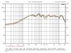
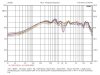
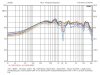
The forward vertical lobe is symmetrical about the +7.44° (from the midpoint between woofer and waveguide) axis, the -6 dB "window" being ~+/- 12.5°.

[The Zilch effect is apparently not operative with this freestanding waveguide, indicating that it may be a baffle-derivative phenomenon.... :) ]
 

Attachments

  • LE14A VPM 10.jpg
    LE14A VPM 10.jpg
    73.1 KB · Views: 25
  • LE14A VPM 15.jpg
    LE14A VPM 15.jpg
    75.4 KB · Views: 25
  • LE14A VPM 20.jpg
    LE14A VPM 20.jpg
    77.9 KB · Views: 24
Last edited:
Hey Zilch!

I have a possible idea for an E-wave and thought I'd toss it out.

I have an old pair of Yamaha 3-ways with dead mids and tweets. :ntwrthy: I know

12 inch woofer run full range with just a cap on mid and tweeter (If it matters)

My question is would these make a good beginner E-wave?
Would that 12 inch woofer reach high enough to work acceptably with the horn/driver selection?


Thanks! :beerchug:
 
I'll measure the vertical polars to see what we've got for a forward lobe.... :yes:

Edit:

The forward vertical lobe is symmetrical about the +7.44° (from the midpoint between woofer and waveguide) axis, the -6 dB "window" being ~+/- 12.5°.

[The Zilch effect is apparently not operative with this freestanding waveguide, indicating that it may be a baffle-derivative phenomenon.... :) ]

I don't really know all of the terminology and implications of the graphs (which is why I am happy to have people like you on board!). What does this mean for the design/build. I currently have the front of the waveguide even with the front of the baffle.
 
My question is would these make a good beginner E-wave?

Would that 12 inch woofer reach high enough to work acceptably with the horn/driver selection?
Most any 12" woofer that is not designed as a subwoofer will play high enough. If you like the bass those speakers make, then go for it.

You don't have to do anything to the Yamahas to verify that the combo will work to your liking -- merely bring out the woofer leads and connect to the eWave driver/waveguide/crossover and listen to how it will sound. If you like the result, then you can commit to modding the cabs as required to complete the build. :yes:


I don't really know all of the terminology and implications of the graphs (which is why I am happy to have people like you on board!). What does this mean for the design/build. I currently have the front of the waveguide even with the front of the baffle.
Any two drivers that are spaced some distance from one another will interfere with each other when playing the same program material. In any multi-way speaker, the drivers are doing that in the crossover region. The interference is manifest as a cancellation, i.e., a dip or notch in the response, whenever the distance from the listener (in this case, the measurement microphone) to each of the two sources is sufficiently different to generate the interference.

In designing the crossover, we "steer" the forward (non-interfering) axis such that it is aimed at the typical listening height, above and below which a characteristic interference pattern progressively develops with greater displacement of the listener from that axis. Many factors limit how much leeway we have in accomplishing this objective using passive crossovers with reasonable numbers and cost of components. Generally, I try to achieve a symmetrical pattern about an axis aimed somewhat upward from the midpoint between the drivers as reference.

Once I saw that your waveguide was more aligned in a vertical plane than mine, I adjusted the filters to achieve essentially the same flat response at a lower angle. You can see that the acoustic crossover frequency went up a bit in the course accomplishing that. My waveguide flange is 1.75" ahead of the woofer flange, and moving it back would aim the axis correspondingly higher. It's trigonometry at this point; the measurements indicate that we have a +/- 12.5° "window" within which to work before the interference would become audible.

I doubt that you'd even hear it, in any case, as notches are less sonically apparent than peaks. If so, you may want to move the waveguide forward on, for example, a 1" - 2" frame behind its flange. In many builds using the QSC waveguide, we've been rear-mounting the woofer on the baffle to assist in achieving the optimum alignment, but that's not an option here. You can see in the curves that constant directivity is working nicely throughout the balance of the spectrum.... :yes:

 
Last edited:
That makes sense to me, thanks.

In the picture I posted yesterday, the waveguidde was about an inch back from the baffle. After I looked at your picture of the testing set up I moved it forward to be even with the baffle, but not quite as far forward as yours, which appeared to extend slightly beyoned the baffle.

If needed, it can be moved forward further just by unscrewing two screws on the bookshelf brackets.
 
Back
Top Bottom