• The move to the new server is done. There are some software and database maintenance updates in process. This has us passing the hat around to help out. We appreciate any donations. Seriously, even a dollar helps. The payment page may be found here - https://www.audiokarma.org/support.html

2385 reconnect PS00 to P400 pin question

I replaced cap C249 with a 47 uf 16 vlt, it had read 69 uf, also removed all of the transistors we were testing , tested and replaced, checked all wires connected to board found no issue but moved each one to make sure none shorting. FM is back ,not sure which of of what i just described repaired it.
 
You moved wires going to the P200 board? It could also be that there is a cold solder joint on the board and when you moved a wire it reconnected. Anyway, at least you know that you don't need to re-tune the FM circuits. Let it warm up and see if it stays good.
 
I let it run for an hour, no issues but ive installed dial string exactly as diagram but 108 comes in where 88 should be. not sure how to make the dial string turn the wheel the opposite way.
 
not sure how to make the dial string turn the wheel the opposite way.
Can you attach a clear photo of your string path taken from the rear of the receiver like the one for my 2252B below so I can see the windings.
Also, a photo of the string going around the tuning wheel.

Screenshot 2026-06-07 160043.jpg
 
Can you attach a clear photo of your string path taken from the rear of the receiver like the one for my 2252B below so I can see the windings.
Also, a photo of the string going around the tuning wheel.

View attachment 3778535
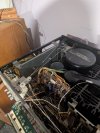
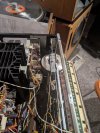
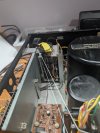
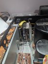
as requested
 

Attachments

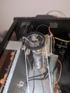
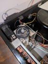
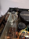
  • PXL_20260607_235001373.jpg
    PXL_20260607_235001373.jpg
    116 KB · Views: 8
  • PXL_20260607_235013968.jpg
    PXL_20260607_235013968.jpg
    128.6 KB · Views: 8
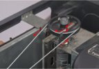
I can't tell from you photos if the string is wrapped correctly around the tuning capacitor pulley because you have the pulley in a different position than the diagram.
Your photo is not very clear. When you move the tuning knob to the RIGHT, does the pointer move to the RIGHT and the tuner cap pulley turn clockwise? Also, neither of you photos show which string the pointer is attached to and where it is on the dial.

Screenshot 2026-06-07 180736.jpg
Screenshot 2026-06-07 180907.jpg
 
I can't tell from you photos if the string is wrapped correctly around the tuning capacitor pulley because you have the pulley in a different position than the diagram.
Your photo is not very clear. When you move the tuning knob to the RIGHT, does the pointer move to the RIGHT and the tuner cap pulley turn clockwise? Also, neither of you photos show which string the pointer is attached to and where it is on the dial.

View attachment 3778615
View attachment 3778616
Yes if you turn the dial wheel to the right, the pointer travels right and the capacitor wheel goes clockwise but that moves the frequencies down but the pointer is moving up in number, i have the pointer off to make it easier to work with the string, it attaches with out glue,
 

Attachments

  • PXL_20260608_013344055.jpg
    PXL_20260608_013344055.jpg
    83.4 KB · Views: 6
  • PXL_20260608_013546529.jpg
    PXL_20260608_013546529.jpg
    97.1 KB · Views: 7
  1. Turn dial wheel to Right, pointer moves to right (OK)
  2. Tuning cap wheel turns clockwise. (OK)
  3. String looks to be OK.
The only other thing that I can think of is that your string is not close enough to the pulley. When you turn the wheel fully to the Left, the capacitor should be in the fully closed position (I think). If you look at the diagram, against your photo above the place where the two strings meet is much farther toward the front of the receiver than in the illustration. I think it should be fully closed when the pointer is all the way to the Left.
 
  1. Turn dial wheel to Right, pointer moves to right (OK)
  2. Tuning cap wheel turns clockwise. (OK)
  3. String looks to be OK.
The only other thing that I can think of is that your string is not close enough to the pulley. When you turn the wheel fully to the Left, the capacitor should be in the fully closed position (I think). If you look at the diagram, against your photo above the place where the two strings meet is much farther toward the front of the receiver than in the illustration. I think it should be fully closed when the pointer is all the way to the Left.
The capacitor is moving fully to the left and to the right, full range. my issue is when the capacitor wheel is moving clockwise (right) the tuning blades below turn to the left, that lowers the frequencies, at the moment the string is moving to the right and with the pointer attached it moves up the dial. Either my tuning below the wheel is traveling wrong, or or some how someone set the frequencies in the wrong direction. If i reverse the way the string is wound on the capacitor wheel it will work but not as per diagram.
 
I reversed the string on the capacitor wheel, opposite of the diagram and now the wheel travels the right way, i have the FM stations working exactly as the dial pointer, 108 is on 108, AM is off but that must mean it was never set up right. I now have an issue when using volume right channel cuts out, i must have a loose wire or connection on the board, will remove and look into. thanks.
 

Attachments

  • PXL_20260608_140618327.jpg
    PXL_20260608_140618327.jpg
    96.5 KB · Views: 3
When you turn the tuning wheel to the left CW (clock-wise), the dial pointer (and dial string) should move to the left, and the drum should turn CCW (counter-clockwise).
When the dial pointer is all the way to the Left, the fins in the tuning capacitor should be fully cllosed. That is the moving fins should fully align with the stationary fins so you basically see no gap. I have a feeling that yours are not positioned correctly so instead of closing, it is actually opening (reducing the capacitance).

Take a photo of the blades on the tuning capacitor when you move the tuning wheel all the way to the left, then another photo when positioned all the way to the right.

Screenshot 2026-06-08 073126.jpg
 
I reversed the string on the capacitor wheel, opposite of the diagram and now the wheel travels the right way, i have the FM stations working exactly as the dial pointer
Maybe there is an error in the SM stringing diagram.
If you look at the SM photo below, it looks like what you say.
Screenshot 2026-06-08 073126.jpg
 
Maybe there is an error in the SM stringing diagram.
If you look at the SM photo below, it looks like what you say.
View attachment 3778854
The first photo is turning capacitor wheel to the right (clock wise) as far as it will go, it turns the tuning wheel to the left, second photo turn the capacitor wheel to the left (counter clock wise) turns the tuning wheel to the right as far as it will go.
 

Attachments

  • PXL_20260608_164303691.jpg
    PXL_20260608_164303691.jpg
    98.4 KB · Views: 3
  • PXL_20260608_164336789.jpg
    PXL_20260608_164336789.jpg
    98.7 KB · Views: 4
Last edited:
Stations i feel are fine now but every time i remove something i get new problems, last one i hope, when listening to fm or am the right channel cuts out intermittently, if i move the volume up or down it comes back, if i lift the rod that come out of the volume it comes back. i removed the board that houses the volume pot, cleaned the pot with deoxit 5 worked it for 20 or 30 times, reflowed all solder points that attached the volume pot no change. still cuts out , am i looking in the wrong place? PS i just remembered when i was using the Marantz in the past i would play with the volume until i got both channels then leave the volume alone.
 
Last edited:
Is there a way to test the volume pot if i have the board out to see if its the volume control or something else?
 
It sounds like it is a real mess to try and get the volume control out. Also, it sounds like the 2385 has a rare special volume control that there is no replacement for unless you find a doner receiver. You might have better access to spray it from the bottom or side with covers off.

Here is the AK thread that discusses it:
2385 Volume pot problem

You should be able to test it with power unplugged and an Ohm meter, but I'm not sure that you can get to the leads easily.
 
It sounds like it is a real mess to try and get the volume control out. Also, it sounds like the 2385 has a rare special volume control that there is no replacement for unless you find a doner receiver. You might have better access to spray it from the bottom or side with covers off.

Here is the AK thread that discusses it:
2385 Volume pot problem

You should be able to test it with power unplugged and an Ohm meter, but I'm not sure that you can get to the leads easily.
Ive already had it out, just need to know how to confirm its the problem thanks
 
Ive got it out again, just need to know how to confirm if its good or defective.
 

Attachments

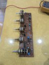
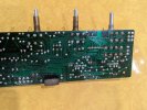
  • PXL_20260609_004153598.jpg
    PXL_20260609_004153598.jpg
    98 KB · Views: 6
  • PXL_20260609_005016401.jpg
    PXL_20260609_005016401.jpg
    116.1 KB · Views: 7
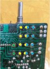
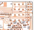
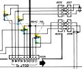
I think this is how it is connected, but I did not trace the full path to the connectors. I believe the center pads with blue/yellow dots are the wiper.
Put your Ohm meter on the yellow dots and turn the control. You should see it go from 0 Ohms to some larger value.
Put your Ohm meter on the blue dots and turn the control and the resistance should be the opposite of the yellow dots.
If you turn it slow you should see a gradual increase in resistance. You want this to be smooth.
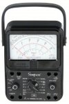
This is where, if you have an old Simpson VOM, you can actually watch the needle move up/down as you rotate the control.
The green dots are for the loudness tap.
Screenshot 2026-06-08 182714.jpgScreenshot 2026-06-08 184523.jpg

Screenshot 2026-06-08 182120.jpgScreenshot 2026-06-08 185343.jpg
 
Last edited:
I think this is how it is connected, but I did not trace the full path to the connectors. I believe the center pads with blue/yellow dots are the wiper.
Put your Ohm meter on the yellow dots and turn the control. You should see it go from 0 Ohms to some larger value.
Put your Ohm meter on the blue dots and turn the control and the resistance should be the opposite of the yellow dots.
If you turn it slow you should see a gradual increase in resistance. You want this to be smooth.
This is where, if you have an old Simpson VOM, you can actually watch the needle move up/down as you rotate the control.
The green dots are for the loudness tap.
View attachment 3779401View attachment 3779409

View attachment 3779397View attachment 3779411

I cleaned then tested volume pot, both channels the same, i feel its good, put board back in no right channel, if i lift the receiver and inch on the right side, right channel comes back on, when i let go its off, there must be a ground wire or the right channel connection in that area, after the pot where would i look for a bad connection?
 
Back
Top Bottom