

You are using an out of date browser. It may not display this or other websites correctly.
You should upgrade or use an alternative browser.
You should upgrade or use an alternative browser.
b&k st-120 power amplifier
- Thread starter groucho69
- Start date
-
- Tags
- b&k channel a no sound st-120
Register to hide this ad


groucho69
Member
Don't guess. You need to learn how to troubleshoot or go through each section like you would a computer flow chart. A volt/ohm meter is your best friend but then again, we don't know your level of expertise.
Basic. I'm an old man who hasn't used these skills for decades.

JoseHH
Super Member
Thank you,
it seems somehow similar to the ST-140 but the components are arranged different so I am not sure if we can use the same schematic.
But there are two fuses on each channel. You need to remove and check if the two fuses are ok on the channel that is not working.
Let us know what you get after you check these fuses.
it seems somehow similar to the ST-140 but the components are arranged different so I am not sure if we can use the same schematic.
But there are two fuses on each channel. You need to remove and check if the two fuses are ok on the channel that is not working.
Let us know what you get after you check these fuses.

JoseHH
Super Member
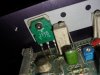
I see some corrosion on one of the legs of the resistor R19 ( the one in front of the ceramic resistor near the 2SJ115 mosfet.
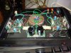
It might be revealing to closely inspect the boards (especially the one that is not working) for corroded tracks underneath. But we can do that later.
Do you have a dim bulb tester?, It is a home built device that uses a filament lamp to limit the current into the unit you are testing. The light bulb goes in series with the mains. If you, do, please power this amplifier via the dim bulb tester, and with the top cover removed.
You need to verify
1-that the red led is on on both boards
2-measure the rail voltages on both both boards. leave all the fuses installed. Measure the DC voltage with the red prong of the volt meter on the fuse, and the black prong of the fuse in the star ground at the center of the toroidal transformer. Do this for left and right channels. It might be close to +50V in one fuse and -50V on the other.
Please let us know what do you get.
It might be revealing to closely inspect the boards (especially the one that is not working) for corroded tracks underneath. But we can do that later.
Do you have a dim bulb tester?, It is a home built device that uses a filament lamp to limit the current into the unit you are testing. The light bulb goes in series with the mains. If you, do, please power this amplifier via the dim bulb tester, and with the top cover removed.
You need to verify
1-that the red led is on on both boards
2-measure the rail voltages on both both boards. leave all the fuses installed. Measure the DC voltage with the red prong of the volt meter on the fuse, and the black prong of the fuse in the star ground at the center of the toroidal transformer. Do this for left and right channels. It might be close to +50V in one fuse and -50V on the other.
Please let us know what do you get.

JoseHH
Super Member
I would have expected the red LED to turn on. But we can leave this for later. If you areworried about the mosfets, before giving up, you can remove the two mosfets, and test them. Look here to see how you can do this with a volt meter. Just note the correct pin out which may be different from that in the tutorial i linked. If the mosfets are ok, then you can put them back and try to diagnose the unit. There is signs of corrosion on the components, so why don't you take a picture of the bottom side of the faulty board?. If you do please post it here so we can see if there is anything visible there.
groucho69
Member
I think these are ToshibaI think my B&K had Hitachi MOSFETs. You may be able to replace them with Exicons.
JoseHH
Super Member
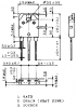
The Toshiba are vertical mosfets, or something similar to more modern mosfets. The Exicons and the Hitachi are laterals. Even the pin out is different (GDS versus GSD)
Please note that this amplifier has source resistors, while the ones that used the Hitachi did not. This has to do with the way the MOSFETS behave as they heat up.
You may still be able to use EXICONS (they are excellent) but note the pin out, and also, you may need to modify the gate driving resistors or the bias network because they have a smaller turn-on voltage so they idle at the correct current which should be around 100mA. I do not know what it is for the Toshibas.
I could not find a schematic for this amplifier but my gut feeling is that the EX-442 may be of some help. If I see clear pictures of the bottom and top of of the boards I might be able to figure out if this is correct.
Here are the datasheets:
Please note that this amplifier has source resistors, while the ones that used the Hitachi did not. This has to do with the way the MOSFETS behave as they heat up.
You may still be able to use EXICONS (they are excellent) but note the pin out, and also, you may need to modify the gate driving resistors or the bias network because they have a smaller turn-on voltage so they idle at the correct current which should be around 100mA. I do not know what it is for the Toshibas.
I could not find a schematic for this amplifier but my gut feeling is that the EX-442 may be of some help. If I see clear pictures of the bottom and top of of the boards I might be able to figure out if this is correct.
Here are the datasheets:
Attachments
JoseHH
Super Member
if you remove the screws, then you need to gentle work their way our with your hands. Alternatively, you may be able to remove the solder, using solder wick or a solder pump to remove the board while leaving the mosfets mounted on the heatsink. If you put any wedge between the back of the transistor and the silicone pad, then you will puncture the silicone and this will need to be replaced. If you want to go down to the bottom of the issue with this unit, then don't worry too much about the silicone pad. Just get the transistors out and test them. They can not be tested in circuit.
You will also have to test the source resistors (the 0.47Ohms ceramic resistors next to the mosfets). And also check the gate resistors which are the 1K resistors that connect to pin 1 of the mosfets.
You will also have to test the source resistors (the 0.47Ohms ceramic resistors next to the mosfets). And also check the gate resistors which are the 1K resistors that connect to pin 1 of the mosfets.
Similar threads

- Replies
- 2
- Views
- 857


- Replies
- 7
- Views
- 6K
