• The move to the new server is done. There are some software and database maintenance updates in process. This has us passing the hat around to help out. We appreciate any donations. Seriously, even a dollar helps. The payment page may be found here - https://www.audiokarma.org/support.html

b&k st-120 power amplifier

if you remove the screws, then you need to gentle work their way our with your hands. Alternatively, you may be able to remove the solder, using solder wick or a solder pump to remove the board while leaving the mosfets mounted on the heatsink. If you put any wedge between the back of the transistor and the silicone pad, then you will puncture the silicone and this will need to be replaced. If you want to go down to the bottom of the issue with this unit, then don't worry too much about the silicone pad. Just get the transistors out and test them. They can not be tested in circuit.
You will also have to test the source resistors (the 0.47Ohms ceramic resistors next to the mosfets). And also check the gate resistors which are the 1K resistors that connect to pin 1 of the mosfets.

Do you really think I'd forget to remove the screws? I'll never make that mistake...again. LOL
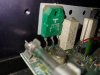
 
OK I'm really stuck. Or rather the fet is stuck. I'm afraid of overstressing the pins. I saw a trick where you use dental floss to get underneath but no help there.
 

Attachments

  • removal.jpg
    removal.jpg
    80.3 KB · Views: 35
Ok, use a ca. 1mm thick metal plate to mask the silicone pad.(not aluminium because it is too soft but some small patch or sheet metal may be 0.5x0.5 inches). Place the metal plate about 2 mm away from the transistor or perhaps on the heatsink but against the edge of the silicone pad. Then, use a small flat screw driver indenting on the metal tab of the transistor, and levering on the sheet metal plate edge. If a 1mm metal plate is too thin to provide sifficient leverage, use a 2mm plate (may be a coin, like a quarter would work). Try to place the tip of the screw driver on the little bevel of the transistor as you see it in the last picture (little shiny copper flat on the upper left corner of the transistor). Use a lever action whith the screw driver while holding the plate with your index finger. This will apply the force directly to the transistor heat spreader and pry off the transistor from the silicone pad. Do not apply force on the green plastic or you may delaminate de transistor. (that means breaking it of course).
The pins have enough compliance and shoud have no problems bending away from the heatsink.
 
Please be carefull. It is better not to power this unit for long time if it has a fault. It may make thing worse.
I think they may have used an adhesive thermal pad. You are going to be a bit more drastic but I would not resort ot a hammer or any kind of pliers for this. If the mosfets test ok (which is likely because they are quite rugged) you will reuse them.

Please try the approach I suggested in my previous post. If they are glued, then wedge a fine screwdriver between the copper heat spreader and the silicone pad and get them out.
You could soften the glue with a heat gun, but you need to be careful not to exceed about 120 degrees Celsius (or 250F) (the limit is 150, but dont heat them that much). Hot air guns can easily exceed this maximum temperature and ruin the transistor.
 
Nothing wrong with the bottom side of the PCB other than some excess of old flux.
These printed circuits are delicate, and the copper foil peels off easily. So be careful when you apply the soldering iron. I
Did you un-solder the mosfets from the board to test them?
If The mosfets test OK, then we need to find what is the malfunction. Could you please take a closeup photo of the component side?.
 
Glad to know that the mosfets test ok.
I am trying to trace the schematic from the pictures but I can not see all the resistor values in the photos. It will take me some time.
In the meantime, since you removed the MOSFETS, please check if the source resistors are ok. They are 0.47 Ohms, They are the big ceramic resistors that are near the Mosfets.
 
Glad to know that the mosfets test ok.
I am trying to trace the schematic from the pictures but I can not see all the resistor values in the photos. It will take me some time.
In the meantime, since you removed the MOSFETS, please check if the source resistors are ok. They are 0.47 Ohms, They are the big ceramic resistors that are near the Mosfets.

The Dales? Wirewound I think.
 
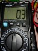
Got the first one out: Dale CP-5 5W47 ohm 10% C9138
The reading is bouncing between .3 and .4
 

Attachments

  • dale1.jpg
    dale1.jpg
    147.1 KB · Views: 7
So none of the resistors is open. At this point, lets try to see if we can figure out a schematic for this board. It does not seem too complex. If you start desoldering transistors to see if one of them is faulty you run in the risk of peeling off pads or tracks that can lift off with the soldering iron. If you feel confident doing this, you could see if the gate drivers are fine or not ( i believe they are 2N5416 and 2n3440)
 
Last edited:
Back
Top Bottom