

You are using an out of date browser. It may not display this or other websites correctly.
You should upgrade or use an alternative browser.
You should upgrade or use an alternative browser.
b&k st-120 power amplifier
- Thread starter groucho69
- Start date
-
- Tags
- b&k channel a no sound st-120


JoseHH
Super Member
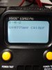
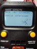
Thank you for doing the measurements. So the Zener diode is a 30V zener.
Ra and Rb will help us knowing the present settings for the adjustable resistors in case that we mess around with them.
Apart from that transistor q12 does work fine if you insert all of its 3 pins in the tester. So it is fine.
The red led if it turns on when you test it and if it has a forward voltage close to 1.7V (Uf or Vf in your tester) i consider it as a working LED.
Put everything back on the board. We have to check that there are no solder bridges or dry solder joints. You have seen now that it is easy to lift traces off the PCB. These printed circuits do not tolerate much soldering iron action. Please be careful with this.
Ra and Rb will help us knowing the present settings for the adjustable resistors in case that we mess around with them.
Apart from that transistor q12 does work fine if you insert all of its 3 pins in the tester. So it is fine.
The red led if it turns on when you test it and if it has a forward voltage close to 1.7V (Uf or Vf in your tester) i consider it as a working LED.
Put everything back on the board. We have to check that there are no solder bridges or dry solder joints. You have seen now that it is easy to lift traces off the PCB. These printed circuits do not tolerate much soldering iron action. Please be careful with this.
JoseHH
Super Member
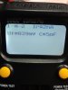
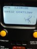
You can continue to test all the transistors in the board. Please be careful with the solder pads and tracks. Please be systematic and take notes of every part you take out test and reinstall. We need to know the location (Q1, Q2 etc) the part number ( 2N5210, 2N3440, etc) and the tests resutls. I am stil stdying the schematic to make sure I have not screwed anything in there. After you tested all the transistors, if they are ok, we may test the board under the dim bulb tester and try to measure some voltages. If you have not yet installed the MOSFETS that is ok. We can test the rest without the mosfets to see what voltages we see in various sections of the circuit to try to see if everything is working as it should, according to our limited knowledge of the schematic.



JoseHH
Super Member
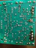
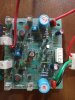
Since none of the components tested bad, we are going to have to assemble the board again and do some tests under a dim bulb tester. We must be careful, because you have been removing and resoldering components so it is very important that a thorough revision of the bottom side is done.

JoseHH
Super Member
Hi there,
Lets review this. You have one channel that is working and one that is not working. On the channel that was not working you checked all the parts and found no faulty parts.
The channel that is working you can leave disconnected from the power supply for now.
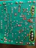
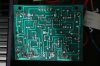
The channel that you were working on has some solder spots that we must revise and retouch. Please re-solder the spots that I circled in red on your picture. Please use flux and apply solder as needed to make a clean and secure solder.
Please use isopropanol to clean up the solder areas I circled in yellow on your picture. And if necessary clean up the ones you retouch with flux so we can clearly see if there are defects or dry solder joints. After that please take a good picture and send it to me via PM or post it here.
If all is good we will need to power the channel that is not working and measure some voltages at various points trusting my schematic since I could not find any other schematic.
Lets review this. You have one channel that is working and one that is not working. On the channel that was not working you checked all the parts and found no faulty parts.
The channel that is working you can leave disconnected from the power supply for now.
The channel that you were working on has some solder spots that we must revise and retouch. Please re-solder the spots that I circled in red on your picture. Please use flux and apply solder as needed to make a clean and secure solder.
Please use isopropanol to clean up the solder areas I circled in yellow on your picture. And if necessary clean up the ones you retouch with flux so we can clearly see if there are defects or dry solder joints. After that please take a good picture and send it to me via PM or post it here.
If all is good we will need to power the channel that is not working and measure some voltages at various points trusting my schematic since I could not find any other schematic.

JoseHH
Super Member
Hello Groucho.
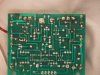
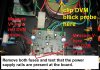
Let us concentrate on the channel that you were checking components. For this channel we need to start verifying that both rails are present at the board when power is applied. For this test remove both fuses at the board and clip the black terminal of your DVM at the star ground of the power supply.
Then set your DVM to measure DC voltage in a scale of 200 V.
Please see the picture for reference:
Then plug the amplifier on via the Dim bulb tester, watch the behavior of the dim bulb as you power the unit on. It should go bright and then dim down and stay dim after that. Please confirm with me that this is indeed what happens.
Then, proceed to measure the voltage present at the input clip of the fuse sockets. Report here what you get for V+ and for V-.
Let us concentrate on the channel that you were checking components. For this channel we need to start verifying that both rails are present at the board when power is applied. For this test remove both fuses at the board and clip the black terminal of your DVM at the star ground of the power supply.
Then set your DVM to measure DC voltage in a scale of 200 V.
Please see the picture for reference:
Then plug the amplifier on via the Dim bulb tester, watch the behavior of the dim bulb as you power the unit on. It should go bright and then dim down and stay dim after that. Please confirm with me that this is indeed what happens.
Then, proceed to measure the voltage present at the input clip of the fuse sockets. Report here what you get for V+ and for V-.
Similar threads

- Replies
- 2
- Views
- 858


- Replies
- 7
- Views
- 6K
