• The move to the new server is done. There are some software and database maintenance updates in process. This has us passing the hat around to help out. We appreciate any donations. Seriously, even a dollar helps. The payment page may be found here - https://www.audiokarma.org/support.html

Kenwood Basic c2 balance adjustment pot

I was messing around with my C2's balance pot a while back. It just felt funky or something, like it turned way too easy. I really cant remember exactly what I did to it either. I really like the way you did that repair ponitora. That was good thinking. I may well order that part and see about putting one in my C2. I think I may have sent you a message over on Epay as well asking you about it. I know that I looked over the C2 Ads over there and one C2 was listed that said the repair was done and listed the parts numbers as well. I am going to have to wait until I find out what the mystery is on the C2 that I have re capped though. I have looked over my work quite thoroughly and I cant seem to find the problem yet.. I have to turn the volume control way too far to get the sound level up and it sounds pretty bad as well. On top of that the right channel is weak..I will find out what I did wrong eventually..
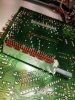
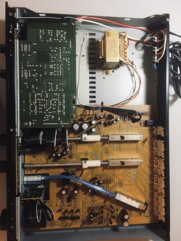
My balance potentiometer was physically damaged so could not be rebuilt. The Alps LPS 704F 250K dual balance pot is functionally identical to the original, but 6mm larger in diameter. It can still fit in the space of the original, and is by the way a better quality component. The LPS 704F solder tabs are larger and spaced wider apart, so the pot body must be rotated away from the board, then wires soldered to the board as shown in the photo. Since the replacement is functionally identical to the original the only difficulty is finding a neat wiring solution, I used the two ribbons shown in the photo. That's it pretty easy no secret about it.View attachment 805570
 
Hi everyone. Thanks for all the advice. It was tricky but I was able to successfully rebuild my balance pot on my c2. (somehow I reassembled it upside-down but.. whatever haha)

I am still having occasional issues due to the input selector being dirty. How do you clean that part? Does it get sprayed in the large blue box area? It didn't look like the standard pentameter I am used to spraying inside of the small hole.
 
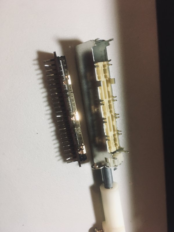
There is really no way to tell you how to clean the selector switches. They must be de soldered from the board marking what one goes back where and disassembled. The internal parts need be cleaned, lubed and everything soldered back. They are time consuming and tedious is the word...
 
Yep, shoot it up on your bench and if I can help in any way let me know. I have done up several C2's and I have some pictures and what not so let me know.
 
Hi vsat88

That would be amazing if you wouldnt mind posting the pictures when you get a chance.

Just wanted to again say thanks for all the helpful comments and pictures people posted about the balance pot, its the only reason I was able to do the repair!
 
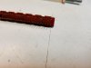
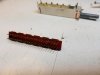
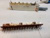
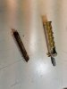
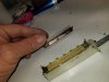
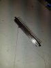
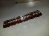
I use Deoxit and plain printer paper on the copper contacts. I let the contacts sit a long time in the Deoxit before using the paper thru the contacts. Very careful with those. They are very small and will disappear on you. They will also bend if you rough house on them. One switch has more positions than the other but they look just alike. Use care to put them back where the came from ! On the metal rails, contacts that connect to the pins (whatever they are called) come in green sometimes ! The oxidation can be pronounced. I use yes, a # 2 pencil eraser on them until I found a "Dremel" tool attachment that had a felt polisher attachment/tip and then I used it with metal polishing compound. That made the job much quicker and easier. Once again..care is the order of the day. I used dielectric silicon (clear) on the rails after the polish. I used solder braid to de solder it all. The pads are tough. I attach one side of the de soldering braid to one of the end of the terminals and followed it all the way down clearing solder at each terminal as I went. Please wet each terminal with new solder first or use rosin. May well use both. On the switches, you have to take them apart right ? Use a very small screwdriver like a watchmaker size but not a tiny one and pry the part that looks like a Y towards each other. It is much more simple than it seems but hard to explain. Those switches are 1: Tough. 2: Very good quality. Take your time. Photograph your work. Do one switch at a time (unless you are impatient like me). Make sure you take in to account where all that stuff came from and put it back. Last but not least. There are phillips screws in the nylon/plastic (whatever it is) connectors that fix the switch to the control rod. Not too tight with those sir. You will see that it takes very little tightening for those to stay in place. Even if you do not get them tight enough the worse that can happen is you will need take the hood off and tune on them a bit. Tighten them too much and well, you know what happens... No need in trying to align all this stuff till you get it all back together. You will see how simple it is to align the knob with the switch using the philips screws , the nylon/plastic spacer and the switch set all the way right or left . I hope you enjoy this project. I did. In fact I have two more I am going to rebuild.
 
Last edited:
Thanks so much! This makes me feel much braver about taking it apart to clean it. The metal underside with the pins just snaps out of the plastic/metal housing?
 
Absolutely not that is what you need the small screwdriver for the metal tabs have to be bent. The metal tabs start out looking like a y when you are done they should be parallel to each other like a Roman numeral 2.
 
Made a go at a different way of cleaning those selector switches tonight. My main pre was giving some trouble so I pulled one of the C2's out of storage I bought to restore and this is what I tried. I sprayed Deoxit in the back hole of the switches nearest to the RCA/Phono jack area then blew compressed air right on thru the switch hoping to force the Deoxit all the way thru the switch. Don't get me wrong, I do not think this is a complete repair but it seems to have worked quite well. This C2 was the dirtiest ones dust wise that I have ran into. The selector switches were trashed out bad with dust. The unit would drop out and sound off real good when they were manipulated. It does not do that now. No crazy sounds as I use them. I worked them about quite a bit as I did this. blowing air all thru the switches. I think this could be quite helpful to those that are not confident about de soldering, taking those jokers apart and restoring them.
 
Thanks! I actually had a chance today to dis-assemble it and clean the selector switch. Overall it went pretty smooth. Thanks for the tip on using the braid.. I had been using a solder sucker before but that was obviously taking waayy too long on those long caterpiller-like selectors.

Thanks for the tip about shooting dexoit through the back. This selector was super corroded though so I am glad I took it apart. Was pretty much totally turned black on each end! Had to go for the eraser, rubbing alcohol, and finish with the dexoit. Used a toothbrush with rubbing alcohol for the rails.

Thanks for all the help, I could not have done it without the pictures and directions! Overall it was easier than rebuliding the balance switch, although it took a little bit longer. Probably 5 hrs start to finish.

Everything seems to be working great now! Sounding great. Its crazy how much better this thing sounds than the cheap backup amp I had in storage. Nice to hear the contrast!

I know the other selector switch will need attention eventually, but going to leave it for now until it has issues. It seemed like the worst corrosion was on the ends of the rails, so since I never touch the other switch and leave it in the middle position, hopefully it will still be fine for a long time.

Was really interesting how the switches work. Seems almost over engineered but I have no idea what was standard in the early 80s.

I feel a lot more confident after doing all those solder joints. I may attempt a full recap in the future, and swapping out the op amp with the one that is a better voltage.


Thanks again for all the help! I hope this information is helpful for other people too!!
 
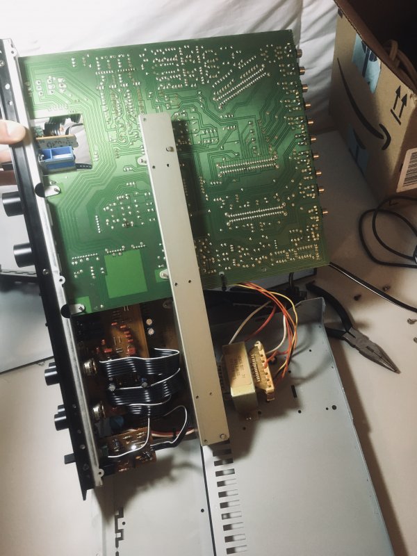
Oh just something I noticed, I was able to carefully flip the board over without disconnecting the transformer. It was a little tricky with the angles but overall not too bad. I just happened to notice the transformer was disconnected in one of your photos, although admittedly it looks a little easier to work on like that and reconnecting the transformer is not super difficult.
 
A lot of work can be done with out disconnecting the transformer. With the work that I do when I have one apart for a restore I take it all apart. I Love the C2 amplifier so when I do one I do it all the way thru. I have never done one as far as upgrading/moding circuits though. Never used any fancy capacitors or anything close. To be honest I do not have the time, inclination, knowledge or money for that. They sound so good with a proper recap, cleaning and op amp upgrade (with standoffs) that has been good for this one .... So far anyway, who knows one day ?? Glad to help. If you took pictures why not upload a few. I would be happy to see them .Oh one more thing, congratulations on getting yours done and thanks for saving another from the scrap heap !
 
Ah gotcha. I figured there was a good reason the transformer was disconnected. Oh just wondering when you recap do you do all of them or just a couple major ones?


Sure thing I posted some photos that I took. Honestly the ones you posted were really good so once I had a good idea of what was going on I stopped taking more photos. But you can see how bad the corrosion was on the rails in the one picture I have of it.
 
I have a C2 and did a few tweaks (caps, opamps, zeners). If you like it, I'd just leave it alone. I didn't find it difficult to update.

I'd probably replace the black foam supporting the blue selector cable. Mine was crumbling and I didn't want any foam bits in the switch contacts.
 
Back
Top Bottom