• The move to the new server is done. There are some software and database maintenance updates in process. This has us passing the hat around to help out. We appreciate any donations. Seriously, even a dollar helps. The payment page may be found here - https://www.audiokarma.org/support.html

Kenwood Basic c2 balance adjustment pot

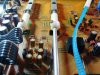
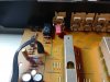
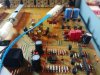
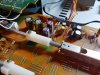
The Alps LPS 704F 250K dual balance pot is functionally identical to the original, but 6mm larger in diameter. It can still fit in the space of the original, and is by the way a better quality component. The LPS 704F solder tabs are larger and spaced wider apart, so the pot body must be rotated away from the board, then wires soldered to the board as shown in the photo. Since the replacement is functionally identical to the original the only difficulty is finding a neat wiring solution, I used the two ribbons shown in the photo.

I checked digi-key and wonder if PDB182-GTRB1-254MN will work.
 
thanks, thats a good point about the foam. i did check it for that reason but it seemed still ok on mine. next time i open it i will probably remove it though.

i would be curious about that balance pot as i reassembled my stem upside down.... doh. still works fine in center position though so not a huge deal.

also my headphone jack pot seems messed up... might try to clean it or replace it in the future.
 
I checked digi-key and wonder if PDB182-GTRB1-254MN will work.
For $2.54 on my next Digi-Key order it would be worth finding out . I bought the Alps that @ponitora said that he used however that has been a long time ago and I have not used it yet. I see that ePay shows none for sale right now. Think if I made up a kit to fix the balance control issue on the C2 and another kit to replace the rear RCA/Phono jack section of the Hafler DH 101 I could get rich ? Lol.
 
For $2.54 on my next Digi-Key order it would be worth finding out . I bought the Alps that @ponitora said that he used however that has been a long time ago and I have not used it yet. I see that ePay shows none for sale right now. Think if I made up a kit to fix the balance control issue on the C2 and another kit to replace the rear RCA/Phono jack section of the Hafler DH 101 I could get rich ? Lol.

Let me know how this goes. Just going to use the resistor fix on mine for now.
 
Will post back when and if I do it. I have been jumping mine out with no resistors and no problems in the past.
 
Are you jumping all three lead holes for each channel together, or just the outside two?
If one jumps out the control across all three leads front and back nothing will work at all as now the signal is shorted. I just flow a bit of solder across the two back and the two front traces . Back right two. Front left two. This is looking at the control shaft. I leave the balance control in place. Keep in mind that the balance control is a common issue but not the only way you could loose a channel. The selector switches often need cleaning (tape and input) well should say they all need cleaning by now and the RCA/Phono input/output solder joints sometimes need re-flowing on some of them. I do all of this when I go into one. No need having take the thing apart over and over chasing an issue. That is just how I have been doing it. Each person does it their own way.
 
Last edited:
If one jumps out the control across all three leads front and back nothing will work at all as now the signal is shorted. I just flow a bit of solder across the two back and the two front traces . Back right two. Front left two. This is looking at the control shaft. I leave the balance control in place. Keep in mind that the balance control is a common issue but not the only way you could loose a channel. The selector switches often need cleaning (tape and input) well should say they all need cleaning by now and the RCA/Phono input/output solder joints sometimes need re-flowing on some of them. I do all of this when I go into one. No need having take the thing apart over and over chasing an issue. That is just how I have been doing it. Each person does it their own way.

I think this exactly what I am going to try.

I've already fully recapped my C2. Replacing some op-amps (with DIP8 sockets for potential rolling) and fixing this issue are next. I was shocked/appalled by the number of RCA jack solder joints that were visibly faulty at this point, and I touched up all of them. I noticed that some other users have added some glue to the plastic shells around the jacks to reduce the immense amount of play they have when connecting and disconnecting cables. Undoubtedly this is why these fail so often.
 
Follow-up to my last post: I jumped the potentiometer and it sounded great, but I ended up with a grounding or feedback issue(?). The right channel will work fine at first, but will then just go out and will be fixed by simply touching the pot contacts for that channel. This is also the only thing that fixes it (besides switching to mono, ofc). I then added a 1k resistor in the generally-described configuration for this workaround, and this seems to be helping.

Anyone had a similar issue with theirs?
 
I think this exactly what I am going to try.

I've already fully recapped my C2. Replacing some op-amps (with DIP8 sockets for potential rolling) and fixing this issue are next. I was shocked/appalled by the number of RCA jack solder joints that were visibly faulty at this point, and I touched up all of them. I noticed that some other users have added some glue to the plastic shells around the jacks to reduce the immense amount of play they have when connecting and disconnecting cables. Undoubtedly this is why these fail so often.

You are firmly up one on me as far as the glue around plastic shells around the jack. I have not read about that one yet. I normally go thru and touch those solder joints up just because I know folk who have had trouble with that but so far I have not had a C2 with that problem. I think I need go ahead and look into the glue thing because I have two more C2's to do. Any heads up as to where the thread is that you read this in ? If not I will just look mine over and I am pretty sure I can find where to put it. Can you tell I like the C1/C2 amps ? I have three of them and I will buy a few more if I find the at the right $.
 
Follow-up to my last post: I jumped the potentiometer and it sounded great, but I ended up with a grounding or feedback issue(?). The right channel will work fine at first, but will then just go out and will be fixed by simply touching the pot contacts for that channel. This is also the only thing that fixes it (besides switching to mono, ofc). I then added a 1k resistor in the generally-described configuration for this workaround, and this seems to be helping.

Anyone had a similar issue with theirs?
Never had a problem with this. I have done I think three this way and never had trouble. Look carefully and see that the flow of solder did not go over onto any of the other pins I guess. You have probably already done this though. Have you tried the resistors on both sides yet or just the one ? Also, do you have the non polar .1uF (I think is 1uF) still hooked up at the amp output (to amplifier) on the back panel ?
 
Never had a problem with this. I have done I think three this way and never had trouble. Look carefully and see that the flow of solder did not go over onto any of the other pins I guess. You have probably already done this though. Have you tried the resistors on both sides yet or just the one ? Also, do you have the non polar .1uF (I think is 1uF) still hooked up at the amp output (to amplifier) on the back panel ?

Yeah, it's odd. Twice I had it open working fine after touching up the flows or adding the resistors, but adding the top case back on nixed the right channel again. It's...odd.
 

Attachments

  • 20191201_180852_HDR.jpg
    20191201_180852_HDR.jpg
    109 KB · Views: 54
  • 20191201_180840_HDR.jpg
    20191201_180840_HDR.jpg
    84.8 KB · Views: 51
  • 20191201_180847.jpg
    20191201_180847.jpg
    107.9 KB · Views: 53
  • 20191201_162532.jpg
    20191201_162532.jpg
    64.6 KB · Views: 54
  • 20191201_180829_HDR.jpg
    20191201_180829_HDR.jpg
    107.3 KB · Views: 52
  • 20191201_180907.jpg
    20191201_180907.jpg
    65 KB · Views: 54
Look below.
 

Attachments

  • 1uF non polar capacitor back panel Kenwood C2.jpg
    1uF non polar capacitor back panel Kenwood C2.jpg
    107.7 KB · Views: 43
Looks like both of those large diameter leads on the mills have broken/lifted the traces in the pictures. Nice re cap btw. Like the parts you used.
 
image 162532 of the top of the balance board looks like the solder does not touch on the back right side...
 
I hung in here for a while to see if you were still posting. Gonna go now but I will check back in. Hope you find the culprit.
 
Back
Top Bottom