• The move to the new server is done. There are some software and database maintenance updates in process. This has us passing the hat around to help out. We appreciate any donations. Seriously, even a dollar helps. The payment page may be found here - https://www.audiokarma.org/support.html

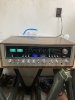
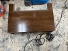
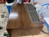
Sansui 9090 receiver

I will take my time with it and I will Eventually get it working.
Not the way you are going. You are likely to introduce any number of new problems as you tromp around on the circuit boards.

To test a transistor properly there are 6 tests not two. Here's a link to a good description of the transistor testing procedure. This link also has a good diagram of the pin out of common transistors.

Here is AK member @EchoWars thread on the topic.

Use the diode test function on your multimeter. Also keep in mind that the metal case of your power transistors is the collector of the transistor.

- Pete
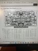
 
On board F-2436 on the Sansui 9090 receiver,Is R-29 and R-30,a 290 ohm fusible resistor,or 390 ohm resistor?pretty sure it’s 290 ohm.Resistor looks like red,white and brown bands.Can’t tell from blurry schematic.
 
Tough to see!
 

Attachments

  • 2CE803AA-43AA-4D84-94FC-95C130188FA6.jpeg
    2CE803AA-43AA-4D84-94FC-95C130188FA6.jpeg
    164.1 KB · Views: 31
  • 0910F079-78E6-41DB-9CAC-46CF4CD11A8A.jpeg
    0910F079-78E6-41DB-9CAC-46CF4CD11A8A.jpeg
    169.2 KB · Views: 27
Sansui modified the F-2436 driver board several times during the 9090 production run. It may depend on what version of the board you have. Also, as a rule, the values on the schematic are often more accurate than the parts list for the board.

You do need to replace the fuse resistors on the driver board but troublesome fuse resistors would NEVER blow the two glass fuses you indicated earlier.

- Pete
 
Well,it is still in protect mode.I’ve checked all eight output transistors 3 times now and all are good.I’ve replaced about 12 resistors on the output board and double checked all the transistors and diodes on that board.With the output board removed,bulb dimmer goes right out but stays in protect.When I place the output board in the socket,bulb dimmer goes bright white.Stumped right now.Tomorrow I will take some voltage measurements on the protection board see if I can figure out what’s going on
 
Well,it is still in protect mode.I’ve checked all eight output transistors 3 times now and all are good.I’ve replaced about 12 resistors on the output board and double checked all the transistors and diodes on that board.With the output board removed,bulb dimmer goes right out but stays in protect.When I place the output board in the socket,bulb dimmer goes bright white.Stumped right now.Tomorrow I will take some voltage measurements on the protection board see if I can figure out what’s going on
You have got the bias trimmers set to minimum? If they are cranked up it will make the DBT go bright!!
 
It's very unlikely there is anything wrong with your protection circuit unless you have been messing with that board. The protection circuit will not turn on the relay if it sees a fault in the amplifier. That's it's job. So unless you have fixed the fault in the amplifier, the relay will never come on. The only thing you need to check on that board are the relay contacts. Look at them closely to see if they are burned/melted.

Is it still blow those fuses? If so, that's the problem that needs to be fixed. You need to focus on that. If no longer blowing fuses, what did you do to keep the fuses from blowing? Those blown fuses are the power supply to the amplifier. The number one reason they blow, is shorted output transistors.

If it's staying in protection with the driver board removed, that's another indication that you have shorted output transistors. When you test them, do all 8 of them give you the exact same test results?

The only voltage test you should do at this point is DC offset. It will tell you the health of the amplifier. Since it's in protection, you need to check it at a point before the protection relay. There is a Blue and a Gray wire coming off the bottom of the power supply board. Measure the DC voltage between each of those wires and chassis ground. The fuses have to be good and the output transistors must be in place to measure this voltage.

One other thing, be sure the mica insulators that separate the case of the output transistors from the heat sink are in place and not damaged. If the case of the transistors touches the heat sink, it can blow a fuse.

- Pete
 
When I place the output board in the socket,bulb dimmer goes bright white
From your wording it seems like you are plugging the board in with the power already on - Don't do this!, always insert (or remove) the board with the power off.

My apologies if this is not the case, but it is why we need complete accuracy when you are describing what you are doing.
 
Last edited:
Not the way you are going. You are likely to introduce any number of new problems as you tromp around on the circuit boards.

To test a transistor properly there are 6 tests not two. Here's a link to a good description of the transistor testing procedure. This link also has a good diagram of the pin out of common transistors.

Here is AK member @EchoWars thread on the topic.

Use the diode test function on your multimeter. Also keep in mind that the metal case of your power transistors is the collector of the transistor.

- Pete
 
Well,the 9090 is back and running.3 blown fuse resistors on the output board.3 bad transistors on the protection board,bad diode on the speaker relay board and a bad speaker relay! No blown output transistors.Dc at the speaker terminals 1mv on both channels,dc milla amps set to 50 on both channels. Said I would get it running and I have!
 
thanks for your vote of confidence!Maybe I know a little more than you thought I did!
 

Attachments

  • EE441D00-F69D-4D1B-B0CE-06D7E583D643.jpeg
    EE441D00-F69D-4D1B-B0CE-06D7E583D643.jpeg
    93.6 KB · Views: 27
  • 59C0DD14-3165-4727-AF3C-8777A7A70182.jpeg
    59C0DD14-3165-4727-AF3C-8777A7A70182.jpeg
    193.9 KB · Views: 28
  • 14671991-D7BA-4739-8CFB-33E86E8268D5.jpeg
    14671991-D7BA-4739-8CFB-33E86E8268D5.jpeg
    130.1 KB · Views: 28
Back
Top Bottom