• The move to the new server is done. There are some software and database maintenance updates in process. This has us passing the hat around to help out. We appreciate any donations. Seriously, even a dollar helps. The payment page may be found here - https://www.audiokarma.org/support.html

Sony 2251 and/or 2250 owners thread

Hello!
I took measurements. I provide a report.
In normal operation (starting the motor), measurements are not possible, since the motor rotates at high speeds; the voltage on its winding is 60 V !!! (took measurements in the first 3-4 seconds). Of course, such a mode of operation of the motor is contraindicated !!!
Conditions for carrying out work and measurements: cut off the power supply to the motor, open the wire from the transformer winding.
To take oscillograms, the motor was rotated by hand.
12V and 9V power supplies are normal.
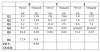
The measured operating modes of the elements (control points) are in accordance with the manual given in the table. A huge question about the modes of the transistor Q3.
The signal from the FG of the desired shape is stable.
Oscillograms (all except pin11 CX-032) fully correspond to the manual in shape, amplitude, frequency; stable. On pin11 of CX-032, the required waveform appears for a very short time (0.5 seconds) at the moment the motor starts rotating and just before stopping. During the rotation of the motor - signal - "straight line".
TEST.jpg
 

Attachments

  • TEST.jpg
    TEST.jpg
    57 KB · Views: 21
60V - yes, with disc installed.
All other measurements - the disc is removed; rotation (to receive the FG signal) by hand.
 
I'm glad I found this thread.
I have a quick question... I recapped the PCB a couple of years ago.
I just rewired the original tonearm, and decided to take a look at the PCB.. then I noticed I missed the two big caps.
4uf 250v and 16uf 50v.
From my understanding the 4uf 250v might be paper in oil (I might be wrong), I was planning on leaving that cap.
The issue is with the 16uf 50v... I don't get if it's bi-polar or not. There are no polarity symbols on the cap, nor any BP info. The manual online doesn't specify any information in regards to polarity.

If anyone can clear up this for me, I greatly appreciate it.
Elna cap.jpg
 
Electrolytic cap = polar. Prolly need to pull it, to find the (+) and (-) posts.

index.php
 
Electrolytic cap = polar. Prolly need to pull it, to find the (+) and (-) posts.

Thanks,
Just removed the cap from the clamp... no symbol.
What's throwing me off is the "AC" part. Since back then things weren't completely standardised. Company could name things what ever they wanted.
 
Thanks,
Just removed the cap from the clamp... no symbol.
What's throwing me off is the "AC" part. Since back then things weren't completely standardised. Company could name things what ever they wanted.


Can you take a photo of the tabs, where the wires were soldered? Must have polarity sign somewhere? :idea:
 
My bet is the black line is negative. With unit off and unplugged, try testing the black lead site to ground and see if you get continuity with a DVM (on ohms setting).
 
Last edited:
My bet is the black line is negative. With unit off and unplugged, try testing the black lead site to ground and see if you get continuity with a DVM (on ohms setting).

Humm... on both leads I get one "beep" and a reading... both readings are pretty close.

Is it starting to look like a BP cap?
 
Yeah, I suppose so. Like two electrolytic polar caps tied in series (-) to (-). ELNA should have stamper "BP" on the cap. Not AC or Electrolytic in big letters. :idea:
 
Yeah, I suppose so. Like two electrolytic polar caps tied in series (-) to (-). ELNA should have stamper "BP" on the cap. Not AC or Electrolytic in big letters. :idea:

Just went to eevblog... and this is what I got from there:

"AC capacitor does not have polarity, but the constructions are generally based on films without any kind of electrolyte. The capacitor has a big volume/capacitance and is expensive also.
Dc Capacitors are based on an electrolyte, that makes a very low capacitance/volume but works only on DC voltage because the electrolyte can't isolate on both direction"


So I guess that settles it.
Also settles the fact I don't have to replace it since it has a construction based on film capacitors.
 
Yes, use a non-polar film cap of similar mfd and voltage rating. Those back-to-back electrolytic NP caps have the same issue as regular electrolytic caps. They all dry out over time. :(
 
Hi! Reviving this old thread. Does anyone know of a replacement dust cover with correct hinges? Is there another Sony model that uses the same one, opening up my chances of locating a dust cover?

Thank you.
 
I lift mine on and off, it's a generic cover.The hinges are hard to come by,I had a pair once and sold them to a member that says he'd been looking for a long time for a set to come up for sale.Patience and a WTB post should help.Love my 2251.
 
Hello!
I took measurements. I provide a report.
In normal operation (starting the motor), measurements are not possible, since the motor rotates at high speeds; the voltage on its winding is 60 V !!! (took measurements in the first 3-4 seconds). Of course, such a mode of operation of the motor is contraindicated !!!
Conditions for carrying out work and measurements: cut off the power supply to the motor, open the wire from the transformer winding.
To take oscillograms, the motor was rotated by hand.
12V and 9V power supplies are normal.
The measured operating modes of the elements (control points) are in accordance with the manual given in the table. A huge question about the modes of the transistor Q3.
The signal from the FG of the desired shape is stable.
Oscillograms (all except pin11 CX-032) fully correspond to the manual in shape, amplitude, frequency; stable. On pin11 of CX-032, the required waveform appears for a very short time (0.5 seconds) at the moment the motor starts rotating and just before stopping. During the rotation of the motor - signal - "straight line".
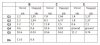
View attachment 2138441

Hi, did you ever fix the issue? I have the same same issue on my 2250 and expect the cx032b is bad and can't find a replacement or even a datasheet for the ic.
 
Back
Top Bottom