• The move to the new server is done. There are some software and database maintenance updates in process. This has us passing the hat around to help out. We appreciate any donations. Seriously, even a dollar helps. The payment page may be found here - https://www.audiokarma.org/support.html

SX 1250 FROM SCRATCH

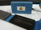
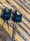
I assume that stv3h diodes may have I-V gradings, a,b,c. Do not know for sure since we have never seen a spec for them.
It's not like the parts lists identified stv3h grading.
Add:
Good eye on noticing the markings on the stv3h diodes, makes sense now why the voltage drop across the six diodes in series is lower than required, where VAS current as measured was to be in spec.
Lessons learnt.
 
Last edited:
What's marked on them? Anything?
Measure and compare against others you have using DMM in diode test mode.
There is a way to replace the stv3h mounted on the amp board PCB heatsink with a new circuit to replace it with a bjt (isolated to-126) and a couple of resistors, the way I did it in my new design. Post #182
 
Last edited:
I measured and they are STV2H's.
I replaced with the STV3H's from my stash (and measured them at 2.1v drop).
The adjustment improved but it's still falls way short.
Using a good board I measured the spread on each driver pair and found the bad board and the good board compare one to one the same at min idle.
Q4 & 6 read 3.02v between collectors. Q7 & 8 read 1.888v between the emitters, Q9 & 10 read 0.888v between the emitters.
The difference is when adjusting the trimmer on the bad board there is barely a voltage spread.
It's like you said, the trimmer resistance is the only variable.
 
This repaired bad board is working up to emitters of the drivers Q9 and 10.
All the voltages are the same across the driver emitter pairs compared to the good boards.
This bad board can't push the outputs up to spec.
You need 1.2v across the base’s of the outputs to get the 100mv idles.
 
Last edited:
One thing to try is change the KSC2073, KSA940 to MJE15032G,15033G, that's what I use in the new design, much better parts.
Although I have used KSC2073, KSA940 as well but the new design has a much larger bias spreader voltage range to work with and is easily modified.
Could even try changing the outputs to MJ2119x
Onsemi KSC2073, KSA940 are EOL and no stock at the distributors. But EVVO makes them, never tried them
This design is like walking on the tight rope.
 
Last edited:
C. Rhodus sent me some nice original amp boards. Popped them in and they tested good. Swapping only the modern transistors (including the 940/2373 p/n's) over and testing, the "Donated" board works perfectly. I failed to (Yet) find the issue. I promise I will continue to work through this unhappy board. It's stripped and the traces will be repaired properly. It was getting to the point where continued work was going to cause unintended trouble. The board needs a fresh start.
The 1250 boards will lift the traces fairly easy.
I'm replacing the caps and trimmers. Then putting it back together.
The shielded signal from the preamp out, back panel RCA, is missing the ground at the 089 board, causing the DC Balance (offset) issue. Got to fix that.
 
Last edited:
The amount of time you have put into it and the condition of it, why not just get a new blank PCB and start fresh. Send me a PM if you are interested, we can work something out. The new design solves a number of problems with the old design and takes the guess work out of the problem's with the old one.
 
It's up and running.
All the front controls are working and the channels are connected to correct sides.
One glitch. The tuner tunes perfectly and the stereo indicator lights but no sound on either channel.
Thinking as I wright, I don't remember connecting a signal wire(s) from the filter amp to the switch assy 094.
The back panel tape in/out RCAs, Adapter RCAs need to be checked for function, and Speaker "B" and "C" connections.
It's getting late and I don't want to take any more chances messing with it.

DSC08057.JPG
 

Attachments

  • DSC08058.JPG
    DSC08058.JPG
    158.9 KB · Views: 10
  • DSC08056.JPG
    DSC08056.JPG
    131 KB · Views: 10
This morning I fixed all the self induced issues and checked the back panel connections. Everything is working well.
One misplaced wire led to other missing wires. Really, I'm patting myself on the back it wasn't worse.
This project was an eye opener into the construction of a vintage receiver. Very interesting learning experience.

I did order Rick's amp boards as a side project for this receiver or more likely, the other minty 1250 I have.
 
That spare 1250 was the key.
The scat doesn’t show the actual chassis grounds. Only the grounds that are connected between boards.
Where the actual grounds are connected are only seen on the spare 1250.
 
Thanks.
It took the two of us. You did a fantastic job putting your half together.
Im glad it’s not a donor anymore.
It really turned out pretty good. It sounds fantastic.
Waiting on a few parts before it can be assembled with the cosmetic bits.
Power switch on the way. One from markthefixer’s stash. That’s kinda cool.
Power socket strip. The one socket in it, is cracked. Usable but it might not be mine eventually.
And it needs most of the knobs and toggles. That is going to hurt. I have a set of the sx-1280 knobs a toggles. Maybe someone will trade me for a set?
 
Thanks.
It took the two of us. You did a fantastic job putting your half together.
Im glad it’s not a donor anymore.
It really turned out pretty good. It sounds fantastic.
Waiting on a few parts before it can be assembled with the cosmetic bits.
Power switch on the way. One from markthefixer’s stash. That’s kinda cool.
Power socket strip. The one socket in it, is cracked. Usable but it might not be mine eventually.
And it needs most of the knobs and toggles. That is going to hurt. I have a set of the sx-1280 knobs a toggles. Maybe someone will trade me for a set?
Like I said before, if you decide to let it go, I'm interested. I still have one of Amos' Walnut cases still in the packaging the way he sent it to me. I think it would be a good fit.
 
"Power socket strip. The one socket in it, is cracked."
Do you mean the three two-blade AC receptacles on the back panel(Switch, Unswitched)?
Post#16
If so, I have a sx-1050 back panel with one on it I can donate.
 
Last edited:
Back
Top Bottom