• The move to the new server is done. There are some software and database maintenance updates in process. This has us passing the hat around to help out. We appreciate any donations. Seriously, even a dollar helps. The payment page may be found here - https://www.audiokarma.org/support.html

SX 1250 FROM SCRATCH

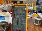
"Adjusting trimmer VR2 the voltage goes from 2.234 to 2.850v"
That explains the reason for low ops bias. Wanting closer to 3.6V.

"Reading 1.714v across R20"
That seems about correct 1.714/620= ~2.8mA

"The voltage at C2/R7 reads the same .550v and is influenced by the trimmer adjustment varying +-20mv but returns to the .550v."
?? One would think it should not return to anything and be constant. 20mV seems low. Need to look at the circuit again.

edit: Maybe real easy ops bias fix is to change the vr2 pot from 470 to 1K ohm.
 
Last edited:
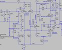
Looking at the DC offset correction circuit, you have on one side a 47K (pulled up to +65V) and 82-ohm to ground. reverse on the other side to -65V. A 470-ohm pot in between
That would mean the adjustment range should be between +/-82 mV.
The input stage runs at around 325uA, so the base current would be at least 325uA/100 for like a miniscule 3uA.
 

Attachments

  • AWH-048-DC OFFSET COMP.jpg
    AWH-048-DC OFFSET COMP.jpg
    64.2 KB · Views: 10
Last edited:
One word, mainly. "Caliche". It can drive up a pool cost to where it doesn't make sense or limits the scope of the project.
But the surface is extremely stable (Mostly rock with a sand binder) and no freezing temperatures. No reason to have deep footings. One underground contractor I knew, dug out a basement for his new house. It was a novelty. I heard tell they have used small charges of dynamite for the prep work, to make some progress through the hardened rock.

Here in the Midwest and most places digging isn't a challenge basements are the cheapest square footage for a home.
 
I think I found the culprit. Sinister!
R37 is reading 1.9K instead of 4.7K.
It’s part of the bias and has an influence to the feedback.
I’m still double checking the board, so far that’s all I see component wise.
Beginning the trace audit.
 

Attachments

  • image.jpg
    image.jpg
    291.1 KB · Views: 2
Huh R37 = 4.7K?
I see it as 4R7-ohm/1W as the base stopper for output drive to PNP (2SB600)
But a high ohmage R37 >> 4R7 would affect the biasing.
While you are at it, check its complement on the NPN side R36 and also R21,22 (100-ohm), emitter resistors R28,29,32,33(0R5-ohm)
Edit: Also R24,25(100-ohm), R26,27(1K)
 
Last edited:
False alarm.
I replaced the undervalued 4.7 ohm 1W resistor and checked all resistors for value. All check good to values.
All the traces check good for continuity between solder connections.
Connecting the board back up, the same fault appears. Basically no bias and no bias adjustment. Offset is still at .550 and stable.
I reflowed all the traces and solder connections and still it’s failing with no improvement.

Thinking now on building some harness extensions so I can get in there and read some voltages better.
This board needs to get fixed. I believe this is the second time I fought with amp board.
I have several stabilizer boards I can rob the pins from. I may have some molex sockets too.
 
False alarm.
I replaced the undervalued 4.7 ohm 1W resistor and checked all resistors for value. All check good to values.
All the traces check good for continuity between solder connections.
Connecting the board back up, the same fault appears. Basically no bias and no bias adjustment. Offset is still at .550 and stable.
I reflowed all the traces and solder connections and still it’s failing with no improvement.

Thinking now on building some harness extensions so I can get in there and read some voltages better.
This board needs to get fixed. I believe this is the second time I fought with amp board.
I have several stabilizer boards I can rob the pins from. I may have some molex sockets too.
I have extra amp boards if you need one.
 
I've been working on the amp(s) most of the morning.
Some headway.
The offset issue was a missing ground at the RCA Main in pre out terminal block. Rick (rcs16) got it right. I had the offset on the bad board but realized later it was reading exactly the same .550v on the other board. I looked at the regulated supplies again but they were spot on at +-65v. I went right to back plate and ran a jumper from the wire wrap ground post to the chassis. And bam! it was back to almost zero on both boards and was adjustable to zero.
No improvement for the idle on the bad board. I did manage to record all the transistor leg voltages.
Getting too hot and delirium was setting in.
I didn’t get a chance to make it easier to read and post the expected voltage.

On DBT
Q3
e (-62.2)
b (-61.74)
c (+61.9)

Q4
e (-62.3)
b (-61.82)
c (-1.214)

Q5
e (+64.0)
b (+63.54)
c (+63.4)

Q6
e (+64.1)
b (+63.63)
c (+1.729)

Q7
e (+0.899)
b (+1.529)
c (+53.9)

Q8
e (-.530)
b (-1.139)
c (-54.1)

Edit Q9, Q10
Full line voltage
Q9
e (+0.891)
b (+0.911)
c (+67.4)

Q10
e (-0.066)
b (-0.573)
c (-67.4)

DSC08050.JPG
 
Last edited:
Something wrong here

Q10 (2SB630)
e (-0.026)
b (-54.1)
c (-50.08)
Schematic shows
Q10b= -1.2
Q10e= -0.65
Q10C= -68.8

Even this is not correct
Q9
e (+0.891), schematic shows 0.65
b (+0.911), schematic shows 1.5
c (+54.2), schematic shows 68.8

why are the +/- supplies so low? Oh yeah you are doing the DBT, get off that thing, once the lamp dims the test is over.
Put a switch in your DBT, to short out the lamp. makes it so much easier.
 
Last edited:
I made edits to Q9 and 10’s voltage readings.
Readings are on full Line voltage.

Edit Q9, Q10
Full line voltage
Q9
e (+0.891)
b (+0.911)
c (+67.4)

Q10
e (-0.066)
b (-0.573)
c (-67.4)

I had a beautiful 1010 get shipped in for a check up and rework. That, I can work on inside.
 
Q9 is not turned on properly, basically off! Something wrong there, with that Vbe being so low.
0.911-0.891

Should be similar to Q10 but opposite polarity.
 
I worked on this board all day. Seriously, eight hours plus. Never, have I had a problem like this. You know, I knew it was going to be an issue with this amp board. That’s why I kept passing on the repair.
I cannot find any faults yet. I tried all my tricks and now I’m starting over again. The poor board is getting a workout as well.
It’s definitely the board because two other good boards work.
I started to pull the ceramic caps off a few at a time. All the silicon has been replaced except for the 1N4005’s. Both STV’s have the correct drop. The trimmers are correct and check good.
I removed most of the components and ohm checked the traces and solder pads with my way cool HP3478A meter. They all check out.
Hopefully a fresh outlook tomorrow.
I’ll post a revised transistor leg readings with it on full line voltage tomorrow morning.
Both sides of that amp are messed up. The PNP side partially works and NPN is virtually dead.
 
As an experiment, How about putting some more resistance in series with the STV diodes Or change vr2 from 470(500) to 1k
Measure the voltages across R15 and R16, both 220-ohm, are they the same, meaning are they in balance?
 
Last edited:
On Full Line Voltage
Q1
e (.539)
c (-62.2)
b (.007)

Q2
e (.543)
c (62.2)
b (.011)

Q3
e (-63.0)
c (+62.6)
b (-62.49)

Q4
e (-62.9)
c (-1.606)
b (-62.52)

Q5
e (+65.1)
c (+64.2)
b (+64.4)

Q6
e (+65.1)
c (+1.462)
b (+64.4)

Q7
e (+0.871)
c (+67.4)
b (+1.497)

Q8
e (-0.997)
c (-67.4)
b (-1.588)

Q9
e (+0.428)
c (+67.4)
b (+0.955)

Q10
e (-0.474)
c (-67.4)
b (-0.990)

As an experiment, How about putting some more resistance in series with the STV diodes Or change vr2 from 470(500) to 1k
Measure the voltages across R15 and R16, both 220-ohm, are they the same, meaning are they in balance?
Drops across R15 and R16.

R15
(0.307)

R16
(0.293)

Moving VR2 made no difference in the drops.

I installed a 1K trimmer and it adjusts up to a bias of 8.5mv with the 1K full trimmer.
I had a meter across the emitters of Q8 and Q9. A emitter reading of the 1.8v actual, the bias is reading 2.5mv.
The trimmer at 1000 ohms reads 3.2v at the emitter Q8,9 and gives that 8.5mv bias reading.

At min bias, the Pre-drivers Q8 and 9 are getting equally hot to the touch. I can leave my finger on them for about three to four seconds before it gets too hot. All the other components are cool to the touch.
 
On Full Line Voltage
Q1
e (.539)
c (-62.2)
b (.007)

Q2
e (.543)
c (62.2)
b (.011)

Q3
e (-63.0)
c (+62.6)
b (-62.49)

Q4
e (-62.9)
c (-1.606)
b (-62.52)

Q5
e (+65.1)
c (+64.2)
b (+64.4)

Q6
e (+65.1)
c (+1.462)
b (+64.4)

Q7
e (+0.871)
c (+67.4)
b (+1.497)

Q8
e (-0.997)
c (-67.4)
b (-1.588)

Q9
e (+0.428)
c (+67.4)
b (+0.955)

Q10
e (-0.474)
c (-67.4)
b (-0.990)


Drops across R15 and R16.

R15
(0.307)

R16
(0.293)

Moving VR2 made no difference in the drops.

I installed a 1K trimmer and it adjusts up to a bias of 8.5mv with the 1K full trimmer.
I had a meter across the emitters of Q8 and Q9. A emitter reading of the 1.8v actual, the bias is reading 2.5mv.
The trimmer at 1000 ohms reads 3.2v at the emitter Q8,9 and gives that 8.5mv bias reading.

At min bias, the Pre-drivers Q8 and 9 are getting equally hot to the touch. I can leave my finger on them for about three to four seconds before it gets too hot. All the other components are cool to the touch.
If I remember correctly, one of those, Q9 I think, has a different pinout than the original. More than once I've installed the new one wrong. Same kind of crazy operation, but no damage done. Once I turned it around everything was fine. Could it be that simple?
 
Check this out:
I was looking for Marks spreader troubleshooting procedure and AI found this. I remember he said "keys to the kingdom".

AI Overview:
The phrase "keys to the kingdom" refers to a famous technical breakdown written by the legendary AudioKarma member Markthefixer (Mark) regarding Pioneer direct-coupled power amplifier stages (such as the SX-1250). It explains how base-emitter voltage steps drop predictably through pre-driver, driver, and output transistors to control idle current and bias. [1]

 
What is the forward drop on a STV3?
I'm getting 1.3v from both STV's
Should it be 2.1v?
Maybe they are not STV3's?
 
All those voltages show the circuit is operating properly except for the bias spreader voltage (Q4,6 bases, -1.6:+1.5) is still insufficient to bias the ops to spec. The schematic shows +/-3.6v
Do the other amp boards have Q8,9 running as hot? I am pretty sure they do but its something to verify.
Up the pot vr2 to 2k and try again
Add:
Stv3h is 3 diodes in series so 3*~0.6 = ~1.8v
It could be out of spec stv but it is a pretty low current going through them, 1.6mA. (0.3v/220).
The design leaves absolutely no wiggle room, changing semis upsets the fine balance they originally had with the original devices.
 
Last edited:
I think I found it.
The STVs on this bad board have a ident of 64c
The good boards ident with 67a and 67b and they read a 2.1v drop.
YEP! I looked at those but discounted it because they both read the same 1.3v drop.
Arff!!!!
 
Last edited:
Back
Top Bottom