• The move to the new server is done. There are some software and database maintenance updates in process. This has us passing the hat around to help out. We appreciate any donations. Seriously, even a dollar helps. The payment page may be found here - https://www.audiokarma.org/support.html

SX 1250 FROM SCRATCH

Putting time into the wiring work.
Dial cord fun later.
The shielded cable is a few days out.
I might start building Rick’s stabilizer power supply in the mean time.
I installed LEDs. It was a no brainer. The receiver was missing them. I do have a stash of saved Pioneer incandescent function lamps but I use those for single replacements on flips and discriminating customers.
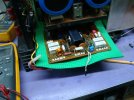
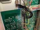
I wanted to show how I install the LEDs.
The board wrapping pins are removed and the LED leads are directly soldered in.
It’s an easy and clean process. Blob the empty pad with solder, cut and strip the leads 2mm, tin the lead and reheat the solder blob while inserting the tined lead.
IMG_0553.jpeg
 

Attachments

  • IMG_0547.jpeg
    IMG_0547.jpeg
    340.2 KB · Views: 25
  • IMG_0548.jpeg
    IMG_0548.jpeg
    346.6 KB · Views: 26
  • IMG_0550.jpeg
    IMG_0550.jpeg
    181.5 KB · Views: 27
Yea but.
There’s only a few and Craig did a proper job. A few out of the transformer (no choice) and a couple from the Molex plug crimps.
I could eliminate those, maybe after all the bugs are worked out.
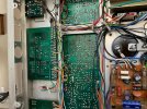
I’m pretty happy with the progress so far. Except for the few splices and what’s going to be all black signal cables, it pretty much OEM spec.
It’s interesting how the factory wires the chassis. The transformer returns are chassis grounded to the other channels filters. There are several circuits that crisscross the bottom chassis. The only way to see this is to have a original 1250 to copy from. The schematic doesn’t show these nuances.
 
Boy that one goes back that I hardly remember doing it as my first rev.
First Check that the bridge rectifier with its glue on heatsink does not interfere with the screws for the bracket on the big ecaps. I recall there was an issue with that one. I have one assembled sitting here never used as I Revd the design to use different rectifiers. Good luck, if it's a problem we can get you the new rev.
 
Yea but.
There’s only a few and Craig did a proper job. A few out of the transformer (no choice) and a couple from the Molex plug crimps.
I could eliminate those, maybe after all the bugs are worked out.
I’m pretty happy with the progress so far. Except for the few splices and what’s going to be all black signal cables, it pretty much OEM spec.
It’s interesting how the factory wires the chassis. The transformer returns are chassis grounded to the other channels filters. There are several circuits that crisscross the bottom chassis. The only way to see this is to have a original 1250 to copy from. The schematic doesn’t show these nuances.
I meant I liked that you ran the lamp wires all the way down to the board instead of splicing to the originals. It just looks so much nicer.
 
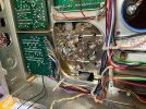
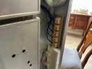
Three days of wiring. Pretty much 15 hours of work.
There are two wire runs left. Both are for the FM antenna to the front end and then, to the back panel connecting terminals.
I’m going to use some 75 ohm coaxial cable. The factory uses something similar but it looks smaller in diameter. Not by much. Something to look into a little more closely.

IMG_0555.jpegL

IMG_0556.jpeg
 
One more connection and its ready for the DBT. I’m kinda scared. I better double check the reg voltage wiring to all the boards.
Markthefixer said he would check until he was confident it will work. I’ll take his advice.
 
If you are uncertain, then power up in stages.
What I mean is disconnect/ unplug the unregulated ~ +/-90vdc between awr-107 ( rectifier/filter PCB) to awr-106 stabilizer, check for the ~ +/-90v, ~ +23vdc on the plug ends that would go into awr-106.
You can leave or optionally disconnect the AC from transformer that go to awr-106 and awm-091 rectifier/protection.
Also disconnect the plugs to the output from the amp modules, awh-048. Check those unplugged connectors for proper ~ +/-72vdc.
Check that soft-start relay energizes, it gets it's 48v coil voltage.
If all okay, start with plugging in the rectified to awr-106, awm-091, check for correct voltages, +/-65,+23,5.4. check that the +/-48v regulators on the phono preamp are correct, go to the buffers on the flat amp.
Finally plug in one amp channel at a time, test for DC offset, bias as usual.
Get the idea, Make any sense?
Good luck
 
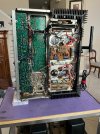
It’s out in the shop getting ready for blast off.
I have the amps disconnected. And went over the wiring for a third time. I started messing with the hinky power switch. Hinky because I had tried and failed to swap out broken toggle with a toggle from a function switch some time back. I totally crushed it. I think I can epoxy it back but that kept me from going any further today. That destruction feeling was in the air. Then my buddy couldn’t get his new HP printer to work so I helped by spilling coffee all over his documents. And the printer is still off line. Not a productive day. Felt like a Bull in a China Shop.
Later I diagnosed a Nakamichi CR-7A issue down to a stuck cam motor. I didn’t screw that up but I was on high alert. There’s still time, and hopefully tomorrow is back to normal.
Thanks rcs16 for the procedure. I will follow it.
 
It’s alive but has a small issue.
All the voltages are spot on across the boards. Polarities correct.
Protect relay engages and DC Balances within .003v.
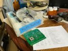
Left amp will not bias (Remains at zero volts). A board I had swapped out to expedite a repair of another unit. It was rebuilt by me but there’s a lingering issue that I now remember.
I was hoping to listen to it this morning but there’s higher priority equipment that needs attention. I’ll look at the board in the air conditioned dining room shop this afternoon.
Remember Mr. C. rondus had the amps and associated circuitry working before he sold it to me. So well done, I used parts for other projects. He definitely made my half of the project easier.
I was saving this 1250 endeavor for after retirement. The 1250 coming together, gives me a smile.

IMG_9074.jpeg
 
Last edited:
Checking the idle and adjustment, it does adjust up and down but only gains 10mv. Zero to 10mv is all its gives up.
I poked around on the amp board checking for visual clues. Pulled Q4, 6, 7 and 8 which were new and tested. They passed.
Set up my troubleshooting procedure and checked the base voltages on those four transistors plus the drivers. I found that the PNP Q8 and 10 base readings are good and move correctly with the trimmer adjustment. The NPN side is dead. Q7 only has 0.3 on the base and doesn't respond to trimmer movement. R21 checks at 100 ohms. There's 64 volts at the emitter of Q6
That's about as far as I went before the heat started to bother me. It's really humid and no clouds in sight. I need that mini-split. I'm thinking of making a spare DBT for the temporary inside shop.

Another related issue is the DC Balance is stuck at .550v with no amount of trimmer it remains at .550v's. On power up it it goes to zero for a moment but then climes to the .550v setting and is stable. Trimmer adjusting will influence it but it will return the .550v incorrect target.
I think a thorough resistor check is in order. I can do that inside.

DSC08049.JPG
 
Last edited:
"There's 64 volts at the collector of Q6"
Are you sure? do you not mean that is the emitter reading.
Schematic shows (65-64.6)/R16(220)= 1.8mA, which should be about half of the total VAS current that is also determined by the voltages they show across R20 (65-63)/620=3.2mA
measure the bias spread voltage variation across Q7,Q8 bases (R21,22) as you turn the pot, VR2. The schematic shows +/-1.8V or total of 3.6V, assuming the spec OPS bias current of 100mA per device.
In my ltspice simulation, it has ~2.8mA flowing thru R20 (620-ohm). Measuring the voltage across R20(620-ohm)
What parts are you using? Q3-10 and outputs?

"Another related issue is the DC Balance is stuck at .550v with no amount of trimmer it remains at .550v's. On power up it it goes to zero for a moment but then climes to the .550v setting and is stable. Trimmer adjusting will influence it but it will return the .550v incorrect target."

measure the voltage at C2/R7, with respect to ground as you vary the pot VR1.
Check your grounds on pins 5 & 6 for continuity. Do they both have separate runs to the common point chassis ground?
 
Last edited:
Yes-emitter Q6.
Thanks for your help.

Component list used:
q1,q2 ksa992
q3,q4 ksc3503
q5,q6 ksa1381
q7 ksc3503
q8 ksa1381
q9 ksc2073
q10 ksa940
q11 ksc1845
 
Last edited:
Does the other channel amp board, use the same complement of components? Does it operate properly in both positions.
Do the measurements I suggested then we'll figure out the next move.
 
I did swap the amps earlier and the bad board followed. It’s something on the board.
As I wright this, I thought I could easily do the troubleshooting in the same amount of time.
Unfortunately follow up troubleshooting is going to have to wait until after the weekend.
I got handyman stuff to do.
Thanks for hanging in here with me. We’ll get this receiver going next week for sure.
 
measure the bias spread voltage variation across Q7,Q8 bases (R21,22) as you turn the pot, VR2. The schematic shows +/-1.8V or total of 3.6V, assuming the spec OPS bias current of 100mA per device.
Adjusting trimmer VR2 the voltage goes from 2.234 to 2.850v

In my ltspice simulation, it has ~2.8mA flowing thru R20 (620-ohm). Measuring the voltage across R20(620-ohm)
What parts are you using? Q3-10 and outputs?
Reading 1.714v across R20.

Measure the voltage at C2/R7, with respect to ground as you vary the pot VR1.
Check your grounds on pins 5 & 6 for continuity. Do they both have separate runs to the common point chassis ground?
The voltage at C2/R7 reads the same .550v and is influenced by the trimmer adjustment varying +-20mv but returns to the .550v.
 
Back
Top Bottom