• Please note that Audiokarma will be offline briefly for updates early on Monday morning, September 28th.

AU-919 complete restoration

Dorian

Active Member
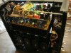
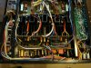
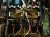
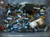
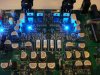
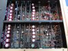
this time the pictures start from the end of the work, so let's go slowly
 

Attachments

  • 1.jpg
    1.jpg
    221.7 KB · Views: 126
  • 3.jpg
    3.jpg
    243.5 KB · Views: 117
  • 4.jpg
    4.jpg
    224.9 KB · Views: 115
  • DSC05969.JPG
    DSC05969.JPG
    122 KB · Views: 116
  • DSC05971.JPG
    DSC05971.JPG
    145.5 KB · Views: 111
  • DSC05972.JPG
    DSC05972.JPG
    134 KB · Views: 113
  • DSC05973.JPG
    DSC05973.JPG
    150.9 KB · Views: 116
  • DSC06100.JPG
    DSC06100.JPG
    148.1 KB · Views: 114
  • DSC06101.JPG
    DSC06101.JPG
    86.2 KB · Views: 113
  • DSC06115.JPG
    DSC06115.JPG
    188.6 KB · Views: 123
Register to hide this ad
I always managed to clean up the glue affected leads on the Noble capacitors in the 3 AU-919's I have reconditioned. The Polystyrene dielectric and radial construction make these capacitors unique and irreplaceable as far as I know.
 
Looks great, not an easy amp to work on. What are your impressions of the unit now that it has been restored?

What's the story behind the green/red LEDs? I see the volume control made it's way to the bin too :confused:
 
Looks great, not an easy amp to work on. What are your impressions of the unit now that it has been restored?

What's the story behind the green/red LEDs? I see the volume control made it's way to the bin too :confused:
Black beauty could not be repaired, so there was no choice but to replace it, I tried with TKD and it was too much work with a short shaft, in the end I put in EIZZ, although I could get the original here and now there are 2 for sale at Kale on ebay
LEDs have significantly less noise, and it is also very useful for visual control in case of a later service
The owner bought that Sansui new and knows how it should sound, he was delighted with the sound after the refresh. That 919 I did the same on the principle of getting the best possible sound from the existing topology, without losing any of the original performance and speed.
 
I always managed to clean up the glue affected leads on the Noble capacitors in the 3 AU-919's I have reconditioned. The Polystyrene dielectric and radial construction make these capacitors unique and irreplaceable as far as I know.
I respect your principle, but each of us works in a different way, personally I have not noticed any difference either sonically or with the instruments if the polystyrene is replaced with mica or PP, and replacing it with a new one gives me security. I have also repeatedly found that the specifications are far out of tolerance or that the capacity is 0. It is unlikely that anyone takes out the elements and measures the tolerances.
 
Output module, brand new original SanKen output transistors used in AU-X1, new and different wiring and transistor arrangement, new emitter resistors. Output module can be switched on and tested for correctness completely without output transistors, it is not necessary to put replacement outputs due to Sanken safety during operation
 

Attachments

  • DSC05213.JPG
    DSC05213.JPG
    95.7 KB · Views: 81
  • DSC05713.JPG
    DSC05713.JPG
    92.7 KB · Views: 78
  • DSC05714.JPG
    DSC05714.JPG
    137.6 KB · Views: 83
  • DSC05717.JPG
    DSC05717.JPG
    128.7 KB · Views: 78
  • DSC05718.JPG
    DSC05718.JPG
    114.1 KB · Views: 76
  • DSC05719.JPG
    DSC05719.JPG
    114.8 KB · Views: 78
  • DSC05721.JPG
    DSC05721.JPG
    114.2 KB · Views: 76
  • DSC05722.JPG
    DSC05722.JPG
    122.7 KB · Views: 77
  • DSC05723.JPG
    DSC05723.JPG
    128.8 KB · Views: 74
  • DSC05724.JPG
    DSC05724.JPG
    121.2 KB · Views: 81
Last edited:
Dorian,...You are a great inspiration!
Beautiful job!
Maybe I should consider replacing those funny clear looking noble caps.
Did you say that the ones that you took out measured zero?
Did he say that guys?
 
Last edited:
Dorian,...You are a great inspiration!
Beautiful job!
Maybe I should consider replacing those funny clear looking noble caps.
Did you say that the ones that you took out measured zero?
Did he say that guys?
Thank you very much. Yes, I said that I found a noble cap with a value of 0 and quite a number far out of tolerance. Taking them out and measuring them is a lot of work and probably no one does it. For me, at least in high speed models like 919, X1, X11, F1, D9, D11, it is a mandatory part of the job. I did not find the mentioned problems with the newer @ series.
 
Very very nice restoration. Did you need to re-stuff the original filter capacitors and would you mind a short explanation about using the LED's instead of regular diodes?
-Lee
 
Very very nice restoration. Did you need to re-stuff the original filter capacitors and would you mind a short explanation about using the LED's instead of regular diodes?
-Lee
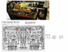
Yes, I always renew the oval filter capacitors and usually the original ones are in very bad condition with half capacity. The procedure has been explained multiple times and there is a picture by picture on the internet of how to do it. Here I found only one picture related to that 919. There are a lot of inquiries about LED. This is nothing new and is often seen in hi-end devices. The reason is that LEDs have less noise than ordinary diodes, especially LEDs made with GaAs technology, but they are very difficult to find. I recently found in a new production that the company BROADCOM offers GaAs LED. I'm looking these days where to buy it, so I'll try it. The pictures show examples of the use of LEDs in other devices, one picture shows the Luxman C-05, and the other a device from the new phono preamp production.
 

Attachments

  • DSC05887.JPG
    DSC05887.JPG
    152.4 KB · Views: 66
  • DSC05905.JPG
    DSC05905.JPG
    98.2 KB · Views: 71
  • GaAs.PNG
    GaAs.PNG
    43.8 KB · Views: 65
  • IMG_0465.JPG
    IMG_0465.JPG
    148.7 KB · Views: 67
Thanks for sharing the info,

I have also seen LEDs used in modern production, user @rcs16 who produces modern designed replacement boards for a handful of desirable 70s audio equipment also uses them. To be honest I am not sure if I have ever seen the LEDs used or recommended in restorations at any time when reworking the existing vintage boards. We're always open to learn and improve our hobby :)

For example, in your photo on F-2839, one LED is capable of acting/replacing a MV-103 varistor. In this case I believe it originally is a triple diode pack? Typically this is often recommended to use a triple 1N4148, however these are not necessarily a shoot on site component.

upload_2022-7-12_9-19-34.png

Regarding the filter capacitor replacements, I noticed you have added bypass capacitors which will reside inside the can. Sansui already designated a spot on F-2845 which serves this purpose. They have three different through hole sizes to accommodate whatever they could get their hands on presumably.

upload_2022-7-12_9-12-1.png
 
The bypass capacitors inside the oval housing are directly on the capacitors because of the inevitable 6-7cm connecting wires and because they are 2 pieces in parallel, it is already a whole science that happens when charging and discharging, but it should definitely be added inside the housing and of course on the PCB as you have already shown themselves, but those inside are more important. The AU-919 is a very high-quality device and if it is restored in the best possible way, it can be considered a hi-end device even today. Sansui engineers were geniuses and their topologies were ahead of their time. The material at that time could not keep up with the quality of the topology and they were still limited by the financial department. So nowadays we have the opportunity to get the result that their engineers and those old men actually wanted, when everything possible is harmonized with new material and some changes, those old men sound comparable to today's hi-end production.
 
Really interesting restoration you show here. ( Also the AU-D9 )
It's good to see different approaches to vintage equipment restoration.
First thing that caught my eye is the local decoupling capacitors on the driverboard that are just 330uF. I have heard about the AU-919 having these in some instances. I am just wondering why you didn't bump them up to 470uF?
Second, if I see correctly you also installed the bypass film capacitors for this electrolytics, was wondering if they were installed originally already ( I have an AU-D907 that has them originally.)
Then about the LEDs. I have read before that they are less noisy, at least then zenerdiodes are in a regulated powersupply. I can not find any information if this applies to the function of the MV-103 that Sansui used.
Do you have some measurements available about the noise, and how much less this is.
Of course we want the less noise, but for me, I would not like this LEDs if it is not a proven benefit.
I mean, to they give 2 uV less noise or some value that lowers you S/N with like 0,001 dB or is there a substantial decrease in noise?
Sorry for all the questions, but I really like to learn more.
 
Last edited:
Those led's look like a very close match to the unobtainable mv-103's, slightly higher forward Vf. How do they behave with current changes?
Certainly more elegant than making up a diode string out of 1n4148's and the likes.
Great thread on the 919 too
 
Really interesting restoration you show here. ( Also the AU-D9 )
It's good to see different approaches to vintage equipment restoration.
First thing that caught my eye is the local decoupling capacitors on the driverboard that are just 330uF. I have heard about the AU-919 having these in some instances. I am just wondering why you didn't bump them up to 470uF?
Second, if I see correctly you also installed the bypass film capacitors for this electrolytics, was wondering if they were installed originally already ( I have an AU-D907 that has them originally.)
Then about the LEDs. I have read before that they are less noisy, at least then zenerdiodes are in a regulated powersupply. I can not find any information if this applies to the function of the MV-103 that Sansui used.
Do you have some measurements available about the noise, and how much less this is.
Of course we want the less noise, but for me, I would not like this LEDs if it is not a proven benefit.
I mean, to they give 2 uV less noise or some value that lowers you S/N with like 0,001 dB or is there a substantial decrease in noise?
Sorry for all the questions, but I really like to learn more.
Uhhh, there are a lot of very specific questions that actually go deep into the engineering waters and you should actually deal with it through 3 different new topics and that outside of the device restoration topics. Now I will try very briefly, every element in topology is a matter of some calculation, which are actually mathematical equations. In relation to the 330 or 470 capacitor with no drop-in and several pages of text, I can only say that nothing would be gained in terms of improvement with an increase in capacity, and with an excessive increase it would only take a turn for the worse. 2. The bypass film must be on the capacitor itself because of the connecting wires. The goal is to eliminate possible peaks of the 100khz or Mhz range, and this will happen because of those few centimeters of connecting wires, and the bypass foils must be right on the capacitors themselves, regardless of the presence of them on the PCB, even the material from which the connecting plugs are made is important , but a detailed explanation would take, as I said, several pages of text and drawings. 3. Regarding noise and LED, circuits should be seen as one functional unit and each element has some function, for example current source, LEDs have low noise and low ESR and overall give better Q-point stability, now I have made it completely complicated. But let's stop there before I have to write a book and believe that big factories like Luxman know what they are doing, and everything that I transmit and do, regardless of the fact that I am an electrical engineer, it was all first made and checked for functionality by a friend of mine who is an absolute genius in audio technique.
 
Those led's look like a very close match to the unobtainable mv-103's, slightly higher forward Vf. How do they behave with current changes?
Certainly more elegant than making up a diode string out of 1n4148's and the likes.
Great thread on the 919 too
I wrote in the topic about au-d9, with such modifications of the mv-103 with LED, it is mandatory when testing the amplifier to bring it back from the clipping state for a longer period of time, because those diodes, among other things, determine and limit the clipping, so that the current characteristics of those LED important, you asked a good question
 
Your explanations are most helpful. There are so few audio courses anymore many of us resort to text books that are (were) written long before the advent of new device availability. I feel that is why all the questions are coming sir. Nice to see you on the Sansui forum as well.
 
Back
Top Bottom