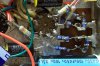
This thread has so much good info, I thought I'd revive it again! Just re-read it after a few months and had a few questions.
Cathode bypass caps are probably chosen originally a value that limited bass response either for the inadequate power supply, speakers used on the amp, output transformer lower bandwidth and or limiting the power consumption of the amp, but most of us use these amps as stand alone units, so all that extra stuff they originally powered is gone. (I generally use between 150uf and 470uf output tube cathode bypass caps on these)
I guess I didn't originally realize the PS limitations of the original whole unit. Suppose I still use the stock Mag AM/FM tuner and separate MPX adapter, would you recommend I downsize the 150uf cathode bypass cap or any/all of the other filter caps? I ended up using 47uf, 100uf, 47uf.
I meant to ask... what is the reason for changing the resistance if you add a volume control?
So that grid to ground resistance doesn't effect the pot/volume control.
Effectively the grid resistor is in parallel to volume pot, it isn't needed for
the circuit to function correctly, it is only there in case the volume pot is
to "Loose contact with the wiper" and create an open tube grid circuit.
(but we make it large enough so it has no/little effect on the pot)
If I'm using a 100k volume pot, only immediately upstream from the input -- connected directly to the other side of the RCA interconnect -- would I want to go with more resistance, such as the 1meg? The 270k in parallel with the pot (it's actually 110k, of course they all seem to be the maximum allowed tolerance off), gives me 78ohms, whereas with the 1m, it's 99ohm which offsets the pot's tolerance deviation nicely. JohnMac reported an improvement in dynamics, so any reason I wouldn't want to just go that way -- realizing that there will be a time when the amp is on and nothing is connected, 1m would still be enough?
Separately, I'm still struggling with having to use a different volume control for iPod/phono vs. the Mag tuner. The stock volume pot is a crazy 3.3M, which predictably sounds awful when using a "modern" source through it. Conversely, if I connect the tuner output via the 100k pot, then it sounds awful. If anyone has any thoughts on how I might "compromise" it would be most appreciated! Modding the tuner is, of course, entirely on the table, unfortunately this part is over my head right, but I want to learn!
I think I've got it. Looks like I can go right from the pin to the positive on the input with the 10k and from the same pin to ground with the 270k. (first time reading schematics and get stuck sometimes). This little bit of info will help me relate other parts of the diagram to the amp.
I would put the 10k resistor right on the tube socket pin, other end of that resistor put the 270k to ground, at that same junction then wired to the pos input of the rca jacks.
JohnMac -- it looks like on your build you've got the 270k resistor to ground
after the 10k grid stopper, but I read it that it should go straight from the RCA input to ground. Did I do mine wrong then? (pic attached)