

You are using an out of date browser. It may not display this or other websites correctly.
You should upgrade or use an alternative browser.
You should upgrade or use an alternative browser.
Magnavox Updated 86-01
- Thread starter cephelps
- Start date

Thespeakerdude8
Super Member
Hey I just wanted to update you guys after my build. I thought my amp was having problems, but in reality it was poor room placement. I am using it in my garage, and I moved my KLH 17's under my work bench on the other side of my garage. I wired them in parallel with my Sony 5" bookshelves which fit neatly on either side of my parts organizers. The amplifier has plenty of power now! Not only does the 4 ohm load help, but my placement of speakers is better for room loading than where I had them before.
I'll post pics once I re-paint the chassis, I had a mishap with the hammertone paint chipping off the cadmium chassis. Guess I didn't rough it up enough before painting.
I'll post pics once I re-paint the chassis, I had a mishap with the hammertone paint chipping off the cadmium chassis. Guess I didn't rough it up enough before painting.

ferninando
Lunatic Member
cephelps, I started a thread for my "new" 8601. Have about same plans as you and will probably end up with a clone.
My question for you is about the big outside caps you used, what's their values, and why 2 and where to get? Seems I read on it somewhere. I may just do the underside placement and leave the can unhooked. Your thoughts welcome.
My question for you is about the big outside caps you used, what's their values, and why 2 and where to get? Seems I read on it somewhere. I may just do the underside placement and leave the can unhooked. Your thoughts welcome.

JohnMac
Addicted Member
I considered putting some caps on top but decided to go underneath. By the time I installed new binding posts, a fuse holder, on/off switch and mounted a lamp holder for a pilot light there's not much room left. Very tight but I think all will fit by adding a terminal strip.
As soon as the rest of the components arrive I'll get started and am sure I'll have some questions.
I connected the volume control from pre/tuner. It worked but it went from minimum to full volume within about 1/4 or less of the full throw of the pot. Bought a 100K X 2 stereo volume pot from RS and the same thing happens. What did I do wrong? Is a volume control on the amp necessary if the pre has one? There is a 1meg on one of the schems. Is that added only if using a volume control?
As soon as the rest of the components arrive I'll get started and am sure I'll have some questions.
I connected the volume control from pre/tuner. It worked but it went from minimum to full volume within about 1/4 or less of the full throw of the pot. Bought a 100K X 2 stereo volume pot from RS and the same thing happens. What did I do wrong? Is a volume control on the amp necessary if the pre has one? There is a 1meg on one of the schems. Is that added only if using a volume control?
Last edited:
ferninando
Lunatic Member
I considered putting some caps on top but decided to go underneath. By the time I installed new binding posts, a fuse holder, on/off switch and mounted a lamp holder for a pilot light there's not much room left. Very tight but I think all will fit by adding a terminal strip.
As soon as the rest of the components arrive I'll get started and am sure I'll have some questions.
I connected the volume control from pre/tuner. It worked but it went from minimum to full volume within about 1/4 or less of the full throw of the pot. Bought a 100K X 2 stereo volume pot from RS and the same thing happens. What did I do wrong? Is a volume control on the amp necessary if the pre has one?
the simple answer to vol control is no. I use a preamp and no vol ctrl on amps. I want the vol/tone/bal of a pre + source sel.
Not all do this. Makes for less junk in the amp IMO.
I'll have to see what size the caps will be to replace the can. On other amps Ive done they've been not to big so can prolly make em fit.
ferninando
Lunatic Member
Good on the no volume control. I'm out of room. So Kegger, it looks like I don't use the 1meg?
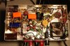
Here's how I intend to lay it out.
what caps you using & source.?
what you got is lookin good.
JohnMac
Addicted Member
I got the Nichicon electrolytics from Mouser, the Orange drops from Antique Electronic Supply and the resistors from Just Radios because they had all of the values that I needed. Sure wish there was one supplier for everything.
The blue cap in the middle would wire up better if it were radial rather than axial but that's what was available.
The blue cap in the middle would wire up better if it were radial rather than axial but that's what was available.

Kegger
R.I.P. 1/12/1966 - 6/1/2017
Without a volume control replace the 1m resistor with something in a 100-270k range.
(that's a grid resistor, the amp will need one)
I don't use a volume control on amps either, I use a separate preamp, but if someone
wanted to connect say cd-player directly to the amp then the volume controls a plus.
One of the reasons you don't get much rotation on the volume control knob is a 6EU7
or an 12AX7 has more gain to it then the EL84 needs, so it's pretty sensitive like that.
(I have another one of these amps, when I get to it I'm changing to lower gain driver)
(that's a grid resistor, the amp will need one)
I don't use a volume control on amps either, I use a separate preamp, but if someone
wanted to connect say cd-player directly to the amp then the volume controls a plus.
One of the reasons you don't get much rotation on the volume control knob is a 6EU7
or an 12AX7 has more gain to it then the EL84 needs, so it's pretty sensitive like that.
(I have another one of these amps, when I get to it I'm changing to lower gain driver)
JohnMac
Addicted Member
I think I've got it. Looks like I can go right from the pin to the positive on the input with the 10k and from the same pin to ground with the 270k. (first time reading schematics and get stuck sometimes). This little bit of info will help me relate other parts of the diagram to the amp.
Last edited:
ferninando
Lunatic Member
I think I've got it. Looks like I can go right from the pin to the positive on the input with the 10k and from the same pin to ground with the 270k. (first time reading schematics and get stuck sometimes). This little bit of info will help me relate other parts of the diagram to the amp.
you got it. just as the schm. shows.
I just got my 8601 and am planning a redo as you are doing. will be interesting to see how the two end up. I gotta oreder parts yet.
Kegger
R.I.P. 1/12/1966 - 6/1/2017
Sorry didn't realize there was a question.
I would put the 10k resistor right on the tube socket pin, other end of that resistor put
the 270k to ground, at that same junction then wired to the pos input of the rca jacks.
It would look just the schematic in the first post, just follow the connections as shown
and it should be pretty straight forward.
I would put the 10k resistor right on the tube socket pin, other end of that resistor put
the 270k to ground, at that same junction then wired to the pos input of the rca jacks.
It would look just the schematic in the first post, just follow the connections as shown
and it should be pretty straight forward.
JohnMac
Addicted Member
I've installed most of the components but have a question about the 20k in the feedback loop. Does it go from the tube to ground or to the + of the speaker terminals? The resistors from the original pre section that I think we are replacing with the 20Ks were wired from the tube to the speakers terminals.
JohnMac
Addicted Member
Got everything in except the 20Ks until I learn how they go. Brought it up slowly then hooked it up. All seems OK but one channel has very low output. I double checked the placement and values of the components and everything seems right. I lack experience in trouble shooting and would appreciate any suggestions.
chameloman72
Active Member
I have a maggie 8606 on the way, I see this is an 8601. What is the difference? Mine looks just like this one but has a different model number??
Similar threads


- Replies
- 4
- Views
- 4K
