• The move to the new server is done. There are some software and database maintenance updates in process. This has us passing the hat around to help out. We appreciate any donations. Seriously, even a dollar helps. The payment page may be found here - https://www.audiokarma.org/support.html

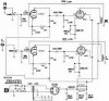
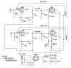
Magnavox Updated 86-01

The only place the caps make a difference in the supply voltage is the first cap in the
supply in cap input power supply on upto about 47uf, beyond that there is no change.

The rest of the caps do filtering an reservoir/energy storage on that amp, the place to
put your reservoir/tank is where an output transformer/output tubes take there supply
from, in this case it is the 150uf cap after the 100ohm resistor, here it is really doing 2
functions supply the reservoir and doing needed filtering/cleaning, as we haven't much
filtering go on before it with a 50uf cap and 100ohm resistor, choke in place of resistor
would do better an we could possibly use a choke with less then 100ohms to get more
voltage out of that supply then as well there to. Single ended amps tend to have little
to no power supply noise rejection so I feel they need to be well filtered, the push pull
amp does have some power supply noise rejection/cancellation but then with generally
running 4 output tubes compared to 2 the capacitance "reserve" wants will go up.

From my perspective the reservoir cap/tank size needs change with the type tubes or
shall we say power of an amplifier, a single ended 6v6, el84 amp 100uf to say high side
of 330uf be the extent of any benefit, but lower then 100uf may not be adequate here.
Where on the 6L6 through kt88's you may want a 220uf to 470uf reserve storage there.

A push pull amp running 4 6v6, el84 say 1.5 times what the single ended version used,
to the tune of 150uf to say on upto 470uf, larger bottles like 6L6-kt88 I'd like to see a
tank of say 330uf on upto say 750uf before the law of "diminishing returns" start to set
in and your larger caps don't really do much for you any more.
(some also feel to large of caps start to degrade the "sound" of the amp) :scratch2:

Now also we need to take into account what it takes to fill these caps, an it can take
a fair amount of power transformer energy when you go to large on those caps, say a
transformer your thinking is on the wimpier side I wouldn't go beyond 220uf in a supply.

Lastly the RC filtering stage feeding the front end, again not a ton filtering done in the
amp prior to this stage so to keep it quiet I used 60uf there, there is no need to build
a reservoir here it is purely for filtering, on most of my amps where I have room for an
adequate supply Before this stage I tend to only run 33uf here as more is not needed.

Cathode bypass caps are probably chosen originally a value that limited bass response
either for the inadequate power supply, speakers used on the amp, output transformer
lower bandwidth and or limiting the power consumption of the amp, but most of us use
these amps as stand alone units, so all that extra stuff they originally powered is gone.
(I generally use between 150uf and 470uf output tube cathode bypass caps on these)

--------

So to sum it up the first cap sets the voltage and 47uf is high side input cap, from say
20uf to 47uf you'll have little change in the output voltage. (47high for tube rectifiers)

150uf-330uf is a decent place/size to upgrade these console amps power supply caps
to in the sections that actually feed the output tubes power, if there's a choke supply
then the stages feeding the front end/drivers 33uf should be fine for those stages but
if no choke and not much filtering upto that point I'd suggest 60uf better value there.

Anyway that is how I treat most console/vintage amp rebuilds that I feel have smaller
then really is adequate to get the job done very well with there original supply designs.
 
Hmm I rebuilt my latest 8601 with this schematic....doesn't do crap on power output. What gives? My RCA SE amp was more powerful than this, heck I think the stock circuit is more powerful. I don't think I'm getting much more than a watt, if that, out of each channel. :saywhat:
 
You must of done something wrong, should be about 3.0w output.
I've built 2 of these an so have a couple others with good results.
(but speakers will tell the story here on these outputs)

(It's not that much different from the original, cleaned up mostly)

If you went separate cathode resistors on EL84's you might want
to check there voltage/current and adjust for more current draw?
(220ohm more current 240ohm less current, in that area)

-------------

If you want to post voltages, plate an cathode of all the tubes we
could probably figure out what is wrong and go from there to fix it.
 
thanks for all the clarification Kegger : )

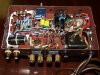
I'm *almost* done wiring this baby - power supply is done, as is the output stage . . . just gotta do the feedback circuit and 6eu7 wiring

I'm not touching the chassis except for a power switch, fuse, and binding posts . .. leaving the crusty chassis as is to reinforce the fact that it came straight from the curb :D
 
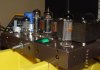
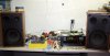
I built the updated 86-01, but with a little more of Kegger's update and it sounds great. I did make a wiring error or two, but caught them in time. There was a sound different with my amp before and after. I can not say that it is louder, but it is more detailed with higher frequencies. It has been running now for 86 hours off and on. The only problem I have had is, it blew a 1 amp fuse. I am not sure if that is too low, but I installed a 1.5 amp and it is fine. As you can see the temporary hook up I have, it sound very nice with these Bozak B301 tempos and a set of B&W 602's. I am building a nice wooden frame for it now and will try other hook ups later. I have two more projects to do, hopefully with Kegger's help. The only thing I can add is to check all of your wiring and components, and good luck.
 

Attachments

  • P6088768.jpg
    P6088768.jpg
    112.6 KB · Views: 180
  • P6118786.jpg
    P6118786.jpg
    57.2 KB · Views: 139
  • P7019299.jpg
    P7019299.jpg
    81 KB · Views: 139
  • UPDATE 86-01C.jpg
    UPDATE 86-01C.jpg
    82.3 KB · Views: 409
You must of done something wrong, should be about 3.0w output.
I've built 2 of these an so have a couple others with good results.
(but speakers will tell the story here on these outputs)

(It's not that much different from the original, cleaned up mostly)

If you went separate cathode resistors on EL84's you might want
to check there voltage/current and adjust for more current draw?
(220ohm more current 240ohm less current, in that area)

-------------

If you want to post voltages, plate an cathode of all the tubes we
could probably figure out what is wrong and go from there to fix it.

I used the shared cathode resistor, althought I might do seperate later...seems to have some crosstalk in the LF as is. I was getting ~12-13v on the cathodes (divided by two is 6.8 ish) and subtracting cathode voltage from the plates gave me an exact 250v plate to cathode voltage. Screens are at about 240v. I did use the stock can for the filters, but that should not make a huge difference right now, right? I plan on replacing it with a jj unit sometime soon, but not if its going to sound the same way. I'm running it on my KLH 17's and it doesn't have any oomph at all. My RCA converted to RH84 drove them to normal levels just fine.
 
Something doesn't look right in your power supply and or your output tube current.

In other words the supply looks a little low, but your output tube current looks high
which could in turn bring the voltage down, looks like you are over 50ma per output
tube, which also means there at about 13w dissipation on the 12w tubes.
(the voltage is close but looks a tad low)

First thing I would probably do is go the separate cathode resistors, get the current
dialed back down to the 40ma range or under, see where the voltage is then retest.

The stock can cap could be hurting voltage and the lack of extra capacitance in the
supply along with that high current could be draining the energy storage now needed.
I would defiantly change the old can cap, it could be hurting the amp quite a bit here.

Getting the output tubes current in line and upgrading the supply caps should go long
way to sussing out and or curing everything that is going on in the amp, even if not I
would suggest it be an needed procedure for however you wire the amp in the future.

But yah supply and tube current I would suggest get updated first then go from there. ;)
 
Huh...every 8601 I've come across had those voltages exactly, which are on par with the schematic. I think the 13w includes screen dissipation so we're good here. I'll try replacing the can cap temporarily with something else, but I know it won't raise the plate supply. Maybe I'll try a diff rectifier, but every maggie 8601 I've come across can't get to more than 280v on the first node.
 
No dought the 8601 power tranny is low on voltage, which is why I use a large input cap
to get the voltage up, all the current draw will kill the original can cap here anyway to. :)
(I'd much prefer a 300v supply to work with for more power on an el84 amp, but hey..)

These EL84 amps with 250v plate to cathode just don't have much power, an don't sound
as good as an amp using 300v+ power supplies, it's just a fact this maggie version is lower
then optimum for these tubes, so power and performance will suffer compared to others.
 
...
(I'd much prefer a 300v supply to work with for more power on an el84 amp, but hey..)

Same here, sweet spot and pretty much the best curves to operate it under.
What do you mean by the current killing the old can cap? I know this goes without saying, but it IS class A so its drawing the same amount of current at all times...as long as the cap can keep up with the discharge frequency (120hz) and provide enough to cut the ripple out then its ok. The amp will be drawing its 100ma (or less) all of the time.
Also, I assume you mean the 150uf cap in your schematic in reference to the input cap? I have always wondered what the safe resistance your power supply needs after the rectifier to keep it from self-destructing with high value capacitors. Any insight into that?
 
Current kiling the can cap an the input cap are the same, the input cap is the first cap
in the supply right after the rectifier in an "cap input" supply, that is the cap that gets
the most beating as there will be more ac on that cap then any other, if that caps old
and tired it can drift in capacitance under load, that first cap "sets" the voltage in the
supply up to a certain capacitance size, you can see this be running the PSUDII power
supply simulator and vary the first cap size, anything under say 47uf will lower voltage
output in the supply and that's why I used a 50uf cap to try an get the most voltage I
could out the power supply from this particular power transformer, I'd had to work with
what was in the amp and extract the most from it that I could.

50uf of capacitance is pushing it for tube rectifiers, I'd much prefer to stay under 33uf
for the first cap in an cap input supply, the second 150uf cap is the tank/reservoir right
where the output tubes/transformer take there voltage from, within reason the rectifier
doesn't care about the size of this one, it was chosen to try an clean up the supply and
to provide extra storage with large output demands, be it bass or heavy output pushing.
(heavy bass notes can drain a supply without sufficient capacitance)

I tried to build the supply as best I could under the restrictions of this particular amp to
keep it pretty clean, most voltage out of the supply and enough reserve capacitance to.
(If I had a bigger chassis and a larger voltage power tranny I would certainly do more) ;)

Also Class A does not mean constant current, it means current constantly up until a point
of clipping and the tube starts to shut off, easy to see it, put your meter on that cathode
resistor with no signal, then go crank the amp up, you'll see the voltage go up as the tube
draws more current with the music, albeit much less change then non class a stages would
have but it will fluctuate with the signal none the less. :)
 
So Keeger, can your approach be extrapolated to the 6v6 and 6bq5 PPamps power supplies second cap(resevoir) as well? One is C input and one is choke input as Im sure you know. and Leave the 1st Cs same value? both 40.
 
Yep, build your tank/resevoir where that output transformer takes it's voltage from, that
is where the amp will benefit most in increasing power supply capacitance, if the voltage
is high enough in your supply (meaning your satisfied with that B+ number) then stick to
say 25 - 33 uf of capacitance on the "input" cap, just increase the following stages is all.
40uf should be fine on a tube rectifier, but if your increasing later down the chain so you
have plenty of capacitance in the supply an your voltage doesn't suffer then 33uf should
be a nice value to stick to, even 20uf if your voltage is still good. (just easier on rectifiers):thmbsp:
 
Thanks for that kegger. I'll have to recheck those numbers but as I recall the PS voltages were all abit
on the high side from the stated schematic values. I did replace all the old PS caps to schematic values.
 
If your voltage is high and you WANT to bring it down start with something like 7.5uf
and see if that gets you closer to where you want to be, as long as you've increased
later in the amp it shouldn't hinder filtering and or power supply performance like that.
(basically you CAN tune the voltage you want from the supply with input cap size)

Generally speaking I find the voltage to be lower then I want on most of these console
amps so I'm not usually looking to lower it but raise it instead, so larger caps often here. ;)
(plus they could usually benefit from a fair bit of extra capacitance, as I find most lean)

Also if using a small input cap, say 10uf or less it may be a nice place to fit a poly cap in. :thmbsp:
 
Thought I'd crash this thread rather than clutter the forum with yet another maggie one. I've been following along in order to understand as much as I can before asking for help. I've done one tube rebuild and was directed by a very detailed pictorial provided by a fellow AKer and there were no mods involved.

To this point I have added a three prong cord, fuse holder and on/off switch. Removed the molex plug and wiring. Snipped the four caps from the pre section. There are for resistors tied to those caps and going to the speaker connects. It looks like they need to go but I'm not sure. Snip 'em?

This is what I understand needs to be done.

Add the 20K resistors for a feed back loop.

Eliminate two of the coupling caps and replace the other two with 22uf.

Replace electrolytics with with values shown on updated schem. I think I'll do seperate cathode resistors, doubling the value of the caps, using a 250k resistor and loosing the 10k resistor.

I noticed an added 10k resistor between the 6EU7 and the 1meg going to the inputs. why was that added?

I didn't intend to replace all of the resistors. I see most of the values were changed, lowered in most cases. How important it is to replace them?

Did I miss anything?

Any help would be much appreciated!

John
 
John,

I saw the Magnavox update and wanted to build it. But wanted to do some changes to it, so I ask for the designer of this circuit and he and others helped me with the changes I wanted to add. As you can look back to the beginning, you will see what I went through to get this amp built. I have added a photo of the original circuit and the circuit the designer and others helped me come up with. I rebuilt the amp as you can see completely. See some of the passed photos.
 

Attachments

  • maggie8601_km_ed1_m2.jpg
    maggie8601_km_ed1_m2.jpg
    74 KB · Views: 146
  • NEWUPDATE.jpg
    NEWUPDATE.jpg
    82 KB · Views: 170
I do see what you went through and with great results.

I've read through the thread many times and it's been very helpful. I'm struggling a little with schematics but am teaching myself to read them and follow the circuits and I think it's starting to sink in.

How does my list of what I need to do look to you?
 
Most if not all of the resistors will have drifted, suggest replacing all of them.
(old used carbon comp resistors, especially less then 1watters drift badly)

not sure what you mean by this:
"Eliminate two of the coupling caps and replace the other two with 22uf."

There are only 2 coupling caps in the amp, from the driver tube to the output
tube and there .22uf on the schem, and that is what I'd suggest to use there.

also:
"I think I'll do seperate cathode resistors, doubling the value of the caps, using
a 250k resistor and loosing the 10k resistor."

That's 250ohm not 250K.. :) (I'd suggest 220ohm actually)

then:
"I noticed an added 10k resistor between the 6EU7 and the 1meg going to the inputs.
why was that added?"

That 10k wasn't really added, more like it "down sized" from the huge one there
originally, it is an grid stopper basically which filters out extreme highs the tubes
won't really produce anyway, acts as a filter so you don't pickup RF/radio signals.

That should about do it.
 
I do see what you went through and with great results.

I've read through the thread many times and it's been very helpful. I'm struggling a little with schematics but am teaching myself to read them and follow the circuits and I think it's starting to sink in.

How does my list of what I need to do look to you?

All so mark your bottom of chassis, Left and Right to keep track of tube sockets, components, to avoid getting Left and Right channels wiring revered.
 
Back
Top Bottom