

You are using an out of date browser. It may not display this or other websites correctly.
You should upgrade or use an alternative browser.
You should upgrade or use an alternative browser.
Magnavox Updated 86-01
- Thread starter cephelps
- Start date

JohnMac
Addicted Member
Well I triple checked my work and still missed my mistake. Took it to a tech in Denver and he spent about 15 minutes to find that a pair of resistors were the wrong value. 270 OHM instead of 270K at the inputs.
He looked the schematics over and questioned two things. He dithced the 180ks and wondered about the high capacitance of the coupling caps.
Anyway it sounds very nice! I'll give it a better audition with a better source and speakers later but so far I'm very pleased. Maybe because this is my second tube project and it didn't explode when I turned it on.
Thanks to Kegger and all others who helped answer my questions. This one forced me to learn to read schematics and relate them to the amp. Can't wait to start the next one. I'm taking a class in
Denver next month and hope to gain a better understanding of why what I do does what it does.
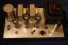
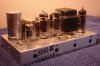
Some pics.
He looked the schematics over and questioned two things. He dithced the 180ks and wondered about the high capacitance of the coupling caps.
Anyway it sounds very nice! I'll give it a better audition with a better source and speakers later but so far I'm very pleased. Maybe because this is my second tube project and it didn't explode when I turned it on.
Thanks to Kegger and all others who helped answer my questions. This one forced me to learn to read schematics and relate them to the amp. Can't wait to start the next one. I'm taking a class in
Denver next month and hope to gain a better understanding of why what I do does what it does.
Some pics.
Attachments


Last edited:

Kegger
R.I.P. 1/12/1966 - 6/1/2017
The 180K resistors aren't "necessary" there to help bias the driver tube better.
(if one was to measure the bias voltage with and without them you'd see it)
The .22uf caps are larger then they need to be, .047uf - .22uf are fine in there.
(I tend to find .22 a little fuller sound cap then a .047 is quite often, I use .22)
Anyway good to see you got it straightened out, if yu feel like taking an posting
voltages (plate and cathode of all tubes) we can see how your circuit is running.
(if one was to measure the bias voltage with and without them you'd see it)
The .22uf caps are larger then they need to be, .047uf - .22uf are fine in there.
(I tend to find .22 a little fuller sound cap then a .047 is quite often, I use .22)
Anyway good to see you got it straightened out, if yu feel like taking an posting
voltages (plate and cathode of all tubes) we can see how your circuit is running.
chameloman72
Active Member
The 180K resistors aren't "necessary" there to help bias the driver tube better.
(if one was to measure the bias voltage with and without them you'd see it)
The .22uf caps are larger then they need to be, .047uf - .22uf are fine in there.
(I tend to find .22 a little fuller sound cap then a .047 is quite often, I use .22)
Anyway good to see you got it straightened out, if yu feel like taking an posting
voltages (plate and cathode of all tubes) we can see how your circuit is running.
The coupling caps in mine are .01uf? Should they be .047 or .22?
Kegger
R.I.P. 1/12/1966 - 6/1/2017
I don't know if I'm taking these measurements correctly. If pin 3 is cathode and pin 7 is plate on the el84s this is what I've got. 20.1v and 20.3v on cathode and 602v on both plates.
UUHHMM, I would get a new meter.. (at least check/replace the battery in it)
Should be around half of those voltages on each. (pin 7 an 3 are correct pins)

JohnMac
Addicted Member
Oops. How's 9.6 and 9.7 at cathodes and 274 at plate.
I'd like to learn to dial the sound in to taste. I find the mids a bit edgy and would like to tone them down. Also wonder if there is too much gain. At anything above normal listening level produces audible distortion. I'd like some head room there. What sections of the circuit control control gain and tone?
The only things that differ in my buid from Keggers design is the removal of the 180K resistors and 470Ks instead of 270ks at the inputs.
Adding on: I played around with different resistors at the input without much noticable intil I put it a 100k and had very little signal. Then I put a 1M to ground and a 100K volume pot. With that I was able to pushl more volume out before it began to distort. How can I replicate that minus the volume pot?
I'd like to learn to dial the sound in to taste. I find the mids a bit edgy and would like to tone them down. Also wonder if there is too much gain. At anything above normal listening level produces audible distortion. I'd like some head room there. What sections of the circuit control control gain and tone?
The only things that differ in my buid from Keggers design is the removal of the 180K resistors and 470Ks instead of 270ks at the inputs.
Adding on: I played around with different resistors at the input without much noticable intil I put it a 100k and had very little signal. Then I put a 1M to ground and a 100K volume pot. With that I was able to pushl more volume out before it began to distort. How can I replicate that minus the volume pot?
Last edited:
chameloman72
Active Member
I would use anything between an .047uf - .22uf for the coupling caps.
.1uf would be right in the middle, .01 would be lower then I would use.
Kegger...you are the man! I had some .1uf orange drops on hand and threw them in there. WOOOOOW what a difference! THANK YOU!

I have the extra money, I am going to order .22uf Auricaps for this beauty!
Kegger
R.I.P. 1/12/1966 - 6/1/2017
Oops. How's 9.6 and 9.7 at cathodes and 274 at plate.
That looks more like it.
Homework assignment for you:
What is the current in the output tubes?
What is the dissipation of the output tubes?
(hint: the info/easy math needed is in this thread) No one cheat and help. :yes:
Kegger
R.I.P. 1/12/1966 - 6/1/2017
I'd like to learn to dial the sound in to taste. I find the mids a bit edgy and would like to tone them down. Also wonder if there is too much gain. At anything above normal listening level produces audible distortion. I'd like some head room there. What sections of the circuit control control gain and tone?
The only things that differ in my build from Keggers design is the removal of the 180K resistors and 470Ks instead of 270ks at the inputs.
Adding on: I played around with different resistors at the input without much noticeable until I put it a 100k and had very little signal. Then I put a 1M to ground and a 100K volume pot. With that I was able to push more volume out before it began to distort. How can I replicate that minus the volume pot?
For tone try different value feedback resistors, from say that 20k on down to an low about 10k.
Try different coupling caps, both type/brand an size with values were mentioned in above posts.
As far as gain, well it's pretty much what you get using the 6EU7 as the driver tube, on my next
one I will be using a different driver tube with a less/proper gain structure, this amp is what it is.
JohnMac
Addicted Member
When I first fired it up I read 281v at plate. After I did the calculations I checked again and the voltage had dropped a little. Over about 40 minutes it continued to drop and finally settled in at 271v. Voltage at the PS caps is 284v. Is this normal?
Anyway here are the specs.
Cathode (both): 9.6v devided by 270 Ohm cathode R = .035a
plate: 271v - 9.6 cathode = 261.4v X .035 = 9.15w
How're we looking?
Adding on: I changed the 22k feedback resistors to 10k which is closer to the orig. 6.8k and with very good results. Upped the bass, rolled off the mids and can greatly increase the volume before it begins to distort. Before I had to cut the mid tone control on the pre way back and if I added any bass it would motorboat, if that's the term. Now I can increase all the tone controls if desired. Getting closer to the "sweet" sound that I'm after.
Anyway here are the specs.
Cathode (both): 9.6v devided by 270 Ohm cathode R = .035a
plate: 271v - 9.6 cathode = 261.4v X .035 = 9.15w
How're we looking?
Adding on: I changed the 22k feedback resistors to 10k which is closer to the orig. 6.8k and with very good results. Upped the bass, rolled off the mids and can greatly increase the volume before it begins to distort. Before I had to cut the mid tone control on the pre way back and if I added any bass it would motorboat, if that's the term. Now I can increase all the tone controls if desired. Getting closer to the "sweet" sound that I'm after.
Last edited:
Kegger
R.I.P. 1/12/1966 - 6/1/2017
Looks pretty good, and yep more feedback will drop "gain", and if not go to far will
flatten the frequency response, the original feedback was 6.8k in some 33k others.
Now I run 10-20k feedback resistors in this amp. (10k currently)
As far as the voltage dropping, yep normal as well, drops as the tubes heat an run.
flatten the frequency response, the original feedback was 6.8k in some 33k others.
Now I run 10-20k feedback resistors in this amp. (10k currently)
As far as the voltage dropping, yep normal as well, drops as the tubes heat an run.

Hippostar
Active Member
To add volume control, change the 270k resistor on the front to 1meg and
add an 100k audio taper pot like say one of the alps ones from radio shack
to control the volume, no added gain is necessary.
I meant to ask... what is the reason for changing the resistance if you add a volume control?
Similar threads


- Replies
- 4
- Views
- 4K
