• The move to the new server is done. There are some software and database maintenance updates in process. This has us passing the hat around to help out. We appreciate any donations. Seriously, even a dollar helps. The payment page may be found here - https://www.audiokarma.org/support.html

Magnavox Updated 86-01

That little maggie is not a bad little amp at all, the design/redesign was basically
a cleaning up of the signal and making things run a bit better then stock really. :)
(your rebuild looks quite nice, there are better circuits then the maggie here)

--------

Since your running single cathode resistors on the outputs you did remember the
value change doubles from what the shared resistor values that were in there. :scratch2:

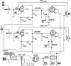
Here is an update to what you have given me, and I did miss on the caps. I noticed that I use the 150uf caps. Today I found a pair of 250ohms resistors, and I will add them to the 300uf caps I have. Thanks for the reminder.
 

Attachments

  • UPDATE 86-01B.jpg
    UPDATE 86-01B.jpg
    81.3 KB · Views: 263
That looks about right..
(build it and we'll check voltages/currents)

250ohm output cathode resistors will drop the current
down, I'd probably go no higher then 240ohm, 200ohm
to 220 should be pretty optimal depending the voltage.
 
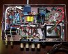
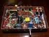
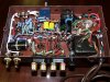
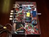
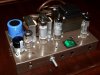
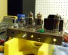
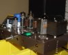
All the wiring is finished and ready for testing. I will fire it up, and try it out later. The design is a nice one, and can't wait to run it. All of the components are of high quality, and wiring is done by very well train hands. (33 yrs Western Electric/AT&T/Lucent Technologies) I will build the wooden frame after the test. I have many high end NOS tubes for this unit, (including a rare quad set of E84L tubes) but I will test with a RCA 6EU7, 2 Magnavox black plate 6BQ5s, and a amperex bugle boy EZ81. I will hook up a high end JVC XL-Z1050 K2 compact disk player in to it, and out to a pair of B&W 602s for now. I will bring it up slowly and run it for an hour if all is OK. I have a few nice control amps to use later, and other more efficient speakers.
 

Attachments

  • P6088763.jpg
    P6088763.jpg
    138.4 KB · Views: 176
  • P6088766.jpg
    P6088766.jpg
    104.3 KB · Views: 108
  • P6088764.jpg
    P6088764.jpg
    115.4 KB · Views: 112
  • P6088767.jpg
    P6088767.jpg
    93 KB · Views: 81
  • P6088765.jpg
    P6088765.jpg
    94.7 KB · Views: 133
  • P6088769.jpg
    P6088769.jpg
    76.8 KB · Views: 171
Looks good, you got everything stuffed in there nicely, yep I'd start/test with your
"lesser" tubes, I generally feel better suggesting some cheap junk speakers as well. :)

Keep us posted..
 
If you notice a little heater growl when you fire it up, it's because the 6.3 volt heater winding is floating above ground. You may not notice it much with the B&W speakers, depending on how sensitive they are.

You can take a couple of 100 ohm resistors and connect them from each tap of the 6.3 volt heater winding to ground. You can see the ones I used on my amplifier. (the two red PRP resistors below the cathode resisitor and bypass cap for the output tubes)

It will help kill some of the AC line noise from the heater winding.
 
I would agree, and I'm sure I did the same with mine, as anytime a heater supply
doesn't have a center tap to tie to ground I create the virtual one as Mike does. :)
(kinda slipped my mine since it was there originally)
 
With no preamp and the only volume control on the amp, I fire it up slowly. I let is warm up for 20 minutes, and heard a very quite amp. I drop a CD into the player, and turn up the volume and was amazed at how clean, clear this amp sounded. I turned up the volume more and let the entire CD play. I have played this CD on several other tube and solid state units, and the magie is very alive and detail. The bass is very nice, and the highs are natural and clear with no sign of any coloration. I can't say enough about the midrange. It just sounds nice! I listen to other bass intense CD, and the bottom end is flat and very nice to listen to. The sound is flat across the entire spectrum crystal clean and clear. After about 2 hours of playing CDs I cranked it wide open for a second or three, and did hear just a little distortion. I will add a preamp to complete the setup. Kegger you did it, one clean sounding little design. What you set out to do, you did it. Wow is not the word for this amp, but something much greater. If any one wants to build this update Magnavox amp, it is worth every penny, and yes it has an improved sound. My cost to build, lets just say I have a lot of extra parts. But it was fun and worth it.
 

Attachments

  • P6118781.jpg
    P6118781.jpg
    76.7 KB · Views: 180
  • P6118785.jpg
    P6118785.jpg
    60.9 KB · Views: 135
Last edited:
Glad it is working right out of the factory! :thmbsp: (keep us posted as to yur findings)
(when yu get a chance post the voltage at each EL84 cathode to check current)

----

Just a bit of info in case you may want it, the 6EU7 has more gain then the EL84
needs so at wide open throttle on your volume control your probably pushing the
EL84 past clipping and that would account for any distortion at that high volume.

Basically it means is the 6EU7 can drive the EL84 further then it needs to be, not
that it's a problem just won't need to crank volume control all the way on the amp.
(I have plans for whole new "improved" circuit for these amps)

Also you won't "need" an external preamp to drive it, you won't gain any "volume".
If you do run a preamp in front of it you may want to turn the volume pot on the
amp to half way or less so you have some room on your preamp's volume control. :)
 
OK, I will get on that today. I was think on the lines of a preamp just for tone and input control. Thanks again for a sweet little amp.
 
If you notice a little heater growl when you fire it up, it's because the 6.3 volt heater winding is floating above ground. You may not notice it much with the B&W speakers, depending on how sensitive they are.

You can take a couple of 100 ohm resistors and connect them from each tap of the 6.3 volt heater winding to ground. You can see the ones I used on my amplifier. (the two red PRP resistors below the cathode resisitor and bypass cap for the output tubes)

It will help kill some of the AC line noise from the heater winding.


Mike I don't hear any hum yet, but what wattage do I use? I plan on trying other speakers, and some other components. I have some 1, 2, and 3 watt 100 ohms metal oxide and some ww.
 
Half watt resistors are fine, but if there is no noise probably wouldn't mess with it.. :)

------

P.S. You are welcome on the amp help..
(I gots quite a few posted around here, when/if you feel like building something else) ;)
 
Mike I don't hear any hum yet, but what wattage do I use? I plan on trying other speakers, and some other components. I have some 1, 2, and 3 watt 100 ohms metal oxide and some ww.

1/2 watt resistors will work fine. They don't necessarily have to be a value of 100 ohms, you can use a bit higher values like 200, 300 ohms, as long as the value isn't too high like 10K or something.

I would guess that once the value is too high, the resistors will start to pull too much current up through them, dropping voltage...a guess...I'm no engineer. You just want to kill some AC noise, not start dropping voltage.

The speakers you are using may just be low enough with regard to sensitivity that the AC heater hum noise isn't objectionable.

If you do try other more efficient speakers, you may notice the heater noise.
I have Klipsch Cornwalls and LaScalas. The Cornwall's are around 98dB in sensitivity, which isn't as much of a issue with respect to AC heater noise.
The LaScala's are around 104dB in efficiency, and they amplifly any sort of little noise that comes up. So AC heater noise will be objectionable.

With the simple CRC type power supply and the virtual center tap using the resistors for the heaters, my little 8600 is plenty quiet with respect to heater/line noise. You gotta put your head in the bass bin to hear much of anything.

Indirectly heated tubes with AC isn't really too difficult to tame. It's when you started heating directly heated tubes with AC like triodes.
Then it becomes kind of a bitch...
 
Glad it is working right out of the factory! :thmbsp: (keep us posted as to yur findings)
(when yu get a chance post the voltage at each EL84 cathode to check current)

----

Just a bit of info in case you may want it, the 6EU7 has more gain then the EL84
needs so at wide open throttle on your volume control your probably pushing the
EL84 past clipping and that would account for any distortion at that high volume.

Basically it means is the 6EU7 can drive the EL84 further then it needs to be, not
that it's a problem just won't need to crank volume control all the way on the amp.

Also you won't "need" an external preamp to drive it, you won't gain any "volume".
If you do run a tin front of it you may want to turn the volume pot on the
amp to half way or less so you have some room on your preamp's volume control. :)

The cathode voltage on the Right EL84 is 7.09 volts. The cathode voltage on the left EL84 is 7.92 volts. I took the time to match every component in this amp, so it must be these used black plate tubes. Is the voltage in the range it should be in? I need to put a new set of tubes in. I was wondering if a pair of these E84L or the Telefunken EL84 would make a big different.
 
What you've got is: (to figure current)
(we will call it 7 and 8 cathode volts respectively)

7volts divided by the 250ohm cathode resistor is .028a or 28ma.

8volts divided by the 250ohm cathode resistor is .032a or 32ma.

It's not bad, I would prefer to see them within say 2ma of each other.
(for relatively even channel output and similar sound from the valves)

----------

Now plate dissipation:

I believe the plate voltage is around 280v. (you might want to measure yours)

280v plate, subtract cathode voltage, say 7.5v here so 272.5 plate to cathode.

272.5 plate to cathode voltage times call it .030a (30ma) gives yu 8.175 watts.

(plate dissipation could defiantly come up, could try a smaller cathode resistor)

----------

EL84's are rated for 12watts plate dissipation, 70% of that is a conservative way
to run the tubes, so 12 times .7 gives you 8.4 watts, pretty close to that 8.175.

----------

In that environment the EL84 should live a long an healthy life, I'd not worry with
even say 10-11w running through the tubes, so take your measurements and roll
away to your hearts content if everything falls into spec. Mine runs in the area of
about 10w dissipation on the tubes as I have a bit more voltage an current then u.
 
It seems I made a mistake. I had the amp plugged in the variable supply set at 109vac. I plugged it in to the wall 121vac. I put a new set of EL84 Brimar tubes in it and checked the voltages again. The cathode voltage on the Right EL84 is 8.51 volts. The cathode voltage on the left EL84 is 8.78 volts. That works out to be 35ma. and 34ma.
I am reading 268vdc on the plates of the EL84s. Now the different is 259.22 times .0345a is 8.943 watts. I guest changing to the right AC voltage, and a new set of tubes made the measurements more usable. It even sounds better. I enjoy listening to the amp even more now. I hooked up a pair of Bozak LS400 speaker and this little amp really sounds great. Great job on your design once again. I will finish it now and show the final unit.
 
Glad to see everything looks pretty good electronics wise.

Yes pic's of the unit in action are always a cool thing here.:thmbsp:

Your voltage is a little lower then mine was, to get the EL84's more
current draw for a bit more power you could lower that 240ohm res
on each cathode down near 220ohm, or even tweak the dual 4.7k's
in the supply a little lower to get more screen voltage, if yu needed. :)
 
I'm really glad this fresh thread is here - got a 86- amp on the bench (finally)

not to go off on a tangent, but would it hurt to raise the 2nd to 220 uf ? reason I ask, I have some scavenged CRT parts, and that's the closet I got to 150 . . . no room to daisy chain 3 47 uf's :D
 
Generally speaking when following a tube amp schematic the only cap you "need" to
try and follow at least close to it's size is the first cap in the supply on an cap input
power supply, it sets the voltage available to the supply, when using the very small
caps like say 1-20uf you can "tune" the voltage, smaller cap lower voltage an so on.
(that is if your looking to get the same voltage out of the supply or tune the volts)

(also watch on a tube rectifier supply the input cap size, I'm maxed out here)
On this rebuild I wanted the most voltage I could get from the supply an only having
a C,RC filter stage before the outputs to get it clean I went rather large caps as well.

So yah on that second stage I'd go as far as say 470uf, as high as 100uf on the 3rd.

Cathode bypass cps on the outputs I'd go anywhere from say 150uf on up to 1000uf.

Cheers!
 
Generally speaking when following a tube amp schematic the only cap you "need" to
try and follow at least close to it's size is the first cap in the supply on an cap input
power supply, it sets the voltage available to the supply, when using the very small
caps like say 1-20uf you can "tune" the voltage, smaller cap lower voltage an so on.
(that is if your looking to get the same voltage out of the supply or tune the volts)

(also watch on a tube rectifier supply the input cap size, I'm maxed out here)
On this rebuild I wanted the most voltage I could get from the supply an only having
a C,RC filter stage before the outputs to get it clean I went rather large caps as well.

So yah on that second stage I'd go as far as say 470uf, as high as 100uf on the 3rd.

Cathode bypass cps on the outputs I'd go anywhere from say 150uf on up to 1000uf.

Cheers!

so are you saying for caps of 10-40uF typ in these mag pwr suplys that you can raise some values up to 100uF and more? Aside from more energy storage when needed, what other benefit does this yield? Anything audible? How are the various suply output voltages affected? Does the same hold true for the Cs on the cathode bias resistor? I understand that by increasing power supply capacitance that you stiffen and better filter the supply voltages which potentially could deepen bass performance. Tru?
 
Back
Top Bottom