• The move to the new server is done. There are some software and database maintenance updates in process. This has us passing the hat around to help out. We appreciate any donations. Seriously, even a dollar helps. The payment page may be found here - https://www.audiokarma.org/support.html

Show us your flea-watts amps!

@FlaCharlie : have you ever attempted to supply the filaments of output direct-heat tubes in a stereo amp with the same DC PSU ? I mean : the L tube and the R tube on the same filament DC supply ?

I never made the test - but I'll do it on a prototype to check - since I plan to built a Compact Stereo Flea-Power amplifier using one 10Y/VT25 output tube par channel, both tubes heating having a common supply 7.5V/3.5ADC.

OK, I may be wrong, but don't see why it would not work, since the DC supply would be heavily decoupled by 47000µF/16V : I don't think that any diaphony issue would occur between the two channel via the common heater supply of the final tubes...

T
 
@FlaCharlie : have you ever attempted to supply the filaments of output direct-heat tubes in a stereo amp with the same DC PSU ? I mean : the L tube and the R tube on the same filament DC supply ?

I never made the test - but I'll do it on a prototype to check - since I plan to built a Compact Stereo Flea-Power amplifier using one 10Y/VT25 output tube par channel, both tubes heating having a common supply 7.5V/3.5ADC.

OK, I may be wrong, but don't see why it would not work, since the DC supply would be heavily decoupled by 47000µF/16V : I don't think that any diaphony issue would occur between the two channel via the common heater supply of the final tubes...

T
No, I've never tried it with output tubes.

As far as I know the rule with directly heated tubes is that, since the filament also serves as the "cathode" any bias scheme that involves the filament requires the tubes to be heated separately. I'm sure Jack understands the technical details much better than I do.

My most recent amps use DHT input tubes which are biased using battery grid bias. This is fixed bias that's not adjustable. Since this doesn't involve the filaments, I can heat them using the same supply.

If you use fixed bias on the output tubes you should be able to share a supply.
 
If you use fixed bias on the output tubes you should be able to share a supply.
Yes, because then one side of the supply can be grounded. The final PS cap would indeed serve to decouple the cathodes in that case. It should be noted that the schematic above presents a possibly significant issue even when it only heats one tube. Signal current flowing through the cathode connects to ground at the wiper of the pot. In addition to the fact the pot serves no purpose and could be replaced with fixed resistors, this arrangement modulates the entire power supply with whatever signal voltage appears at the filament connections. This means the PS is effectively in parallel with the cathode, and any path to ground through the supply will render it part of the signal path. That path to ground exists in the form of leakage through the power transformer. This will affect the signal at higher frequencies if it's significant relative to the resistor values from cathode to ground. In addition, common mode noise can be transferred through the transformer, and that will impact on the signal path. These effects could be mitigated by removing the balance pot and connecting the ends of the filament to ground through two equal value resistors that are sufficiently bypassed. However, that would require two large electrolytics and would not be my preferred method for heating the tube.

Jack
 
It should be noted that the schematic above presents a possibly significant issue even when it only heats one tube. Signal current flowing through the cathode connects to ground at the wiper of the pot. In addition to the fact the pot serves no purpose and could be replaced with fixed resistors, this arrangement modulates the entire power supply with whatever signal voltage appears at the filament connections. This means the PS is effectively in parallel with the cathode, and any path to ground through the supply will render it part of the signal path. That path to ground exists in the form of leakage through the power transformer. This will affect the signal at higher frequencies if it's significant relative to the resistor values from cathode to ground. In addition, common mode noise can be transferred through the transformer, and that will impact on the signal path. These effects could be mitigated by removing the balance pot and connecting the ends of the filament to ground through two equal value resistors that are sufficiently bypassed. However, that would require two large electrolytics and would not be my preferred method for heating the tube.

Jack
I assume your comments apply to @kurorin 's amp - the one that uses the 71A or 12A as an output tube.
 
No, I've never tried it with output tubes.

As far as I know the rule with directly heated tubes is that, since the filament also serves as the "cathode" any bias scheme that involves the filament requires the tubes to be heated separately. I'm sure Jack understands the technical details much better than I do.

My most recent amps use DHT input tubes which are biased using battery grid bias. This is fixed bias that's not adjustable. Since this doesn't involve the filaments, I can heat them using the same supply.

If you use fixed bias on the output tubes you should be able to share a supply.

I see - Thanks @FlaCharlie ! :cool:

So I'll test this :

1696349902332.png

T
 
I'd be interested to see the schematic. AFAIK, Magnequest was the only company to ever make a decent multi-tap headphone OPT, and Mikey priced them commensurate with performance. The Grado SR60i phones are extremely sensitive. I tested them recently and found that anything above 20mV RMS is very loud. That represents less than 1mW at 32Ω. This opens the door for many configurations of amplifiers to drive them successfully. I've been wanting to use the RK34 for several years, and this looks like a good opportunity. :)

Jack
Vanderveen also makes a headphone transformer with multiple taps. https://www.mennovanderveen.nl/index.php/nl/producten/other/vdv-800-v-hph-detail. He has a sterling reputation for his other designs so I’m sure these would be great as well.
 
DSCF3592.jpg

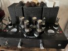
Intact Audio nickel plate choke loaded 6A6s > cap coupled > 2A3s > Tamura F7002 permalloy output transformers - more details :)
 
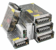
@FlaCharlie : for supplying from 220-240VAC à 7.50VDC voltage with 4-5A (think VT25/10Y project), can you recommend me a super-compact integrable power supply ?

I found nothing... :confused:
 
@FlaCharlie : for supplying from 220-240VAC à 7.50VDC voltage with 4-5A (think VT25/10Y project), can you recommend me a super-compact integrable power supply ?

I found nothing... :confused:
The only ones I have any experience with are the Meanwells but I'm sure there are numerous other brands too. I'd just buy them from a major electronics supplier, not something you find on eBay or AliExpress. I believe DigiKey has warehouses in Europe too but, if not, other suppliers should have them.

If you're heating each tube separately, this one should work. This is the same one I'm using to heat each of the 2E22s in the Cockeyed Monkey. The 2E22 draws 1.5A vs 1.25A for the 10.


If you're planning on heating them both with one supply, which would require you to use fixed bias, this one should work:


The key is to de-rate the current spec considerably but I don't really know for sure exactly how much de-rating is necessary.
 
@FlaCharlie : for supplying from 220-240VAC à 7.50VDC voltage with 4-5A (think VT25/10Y project), can you recommend me a super-compact integrable power supply ?

I found nothing... :confused:
I have modified the 5V 4A switching supplies to provide 6.3V, but don't know if they can be extended to 7.5V. My suggestion is to buy a 5V 10A (50W) or 12V 5A (60W) version and try it. The voltage can be adjusted by changing the resistors around the voltage trim pot, including the feedback resistor from the pot back to the regulator circuit. These supplies are very inexpensive.

Screen Shot 2023-10-06 at 3.09.30 PM.png
Jack
 
Thanks @FlaCharlie ! :cool: :cool: :cool:

For the moment, I made a first heating test using old-conventional solutions :

1696623744428.png

This is not ideal but it works, despite that the temperature of the diodes D1 and D2 reaches 45-50°C, placed on a 100x150x2mm alminium plate...

T
 
@FlaCharlie - following our conversation about cathode bias of DHT :

In order to check if a single DC heater source plus stereo cathode bias operation was doable, I made some measurements on my U-300B to notice the residual signal voltages accross the heater and the decoupled cathode resistor :

View attachment 3004836

Unless mentioned by a double arrow, signal voltages are measured to GND.

We observe here that :

- there is a noticeable signal voltage /GND at each end of the heater, higher at low signal frequencies.

- there is no signal voltage accross the heater ends at any frequency.

- there is a small signal voltage accross the cathode bias resistor at low frequencies.

Conclusion :

- the presence of a residual signal voltage is due to an always imperfect decoupling of the cathode resistor and heater ends /GND, otherwise it would work like a fixed bias operation.

- adding a pair of big capacitors at the heater ends /GND would improve decoupling, but there will be a small remaining signal at very low frequencies, since the decoupling capacitors do not have an infinite value by the way.

This drives me to the following question : if operating in fixed bias, the cathode resistor is cancelled, but the balance pot still remains, so will the signal voltage accross the filament ends... Which is the most noticeable signal voltage residue, according to the measurements made above. Therefore, I am not sure that shifting from cathode bias to fixed bias is the real cure, finally - unless the heater balance pot could be removed...

T
I would suggest that you start a new thread to discuss these technical aspects further. It seems to me that this thread is primarily intended to be a simple "show and tell" thread for people to post pics of their flea power amps. The particular design issue you're interested in probably doesn't apply to the majority of amps shown here, since many of them don't use directly heated tubes.

I'm not well versed in the technical aspects of all this so my build simply follows "conventional wisdom". @TriodeLuvr and others can surely provide more insight.

A new thread dedicated to this would generate valuable discussion without changing the nature of this long running thread. It would also allow future readers to find the information easier if it's not buried in a general, wide-ranging, thread like this one.
 
Last edited:
I would suggest that you start a new thread to discuss these technical aspects further. It seems to me that this thread is primarily intended to be a simple "show and tell" thread for people to post pics of their flea power amps. The paricular design issue you're interested in probably doesn't apply to the majority of amps shown here, since many of them don't use directly heated tubes.

I'm not well versed in the technical aspects of all this so my build simply follows "conventional wisdom". @TriodeLuvr and others can surely provide more insight.

A new thread dedicated to this would generate valuable discussion without changing the nature of this long running thread. It would also allow future readers to find the information easier if it's not buried in a general, wide-ranging, thread like this one.

Thanks - I experimented a satisfactory common heater + cathode bias solution in the meantime - cheers !

T
 
Back
Top Bottom