You are using an out of date browser. It may not display this or other websites correctly.
You should upgrade or use an alternative browser.
You should upgrade or use an alternative browser.
Opinions on state of AU-20000 sought
- Thread starter KeithD
- Start date
-
- Tags
- sansui au-20000
Register to hide this ad

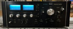
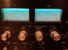
Externals are not bad. A few scratches on the top. Original lamps on the meters were replaced with blue LEDs
First, PS area. I tried to pull this card out for a closer look, but was not able to wiggle it out. Not wanting to break anything, I left it be. A few things I noticed, the board is darker than the other boards, which I assume is due to heat. Second, someone added large pieces of aluminum to the original heatsinks. A number of capacitors have been replaced, not sure if appropriate ones were used in various locations. The two large e-caps on F-2512 look very tired and in sore shape. Top is bulging on each. I pressed on the top of each and it was firm/could not be pushed in.
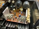
First, PS area. I tried to pull this card out for a closer look, but was not able to wiggle it out. Not wanting to break anything, I left it be. A few things I noticed, the board is darker than the other boards, which I assume is due to heat. Second, someone added large pieces of aluminum to the original heatsinks. A number of capacitors have been replaced, not sure if appropriate ones were used in various locations. The two large e-caps on F-2512 look very tired and in sore shape. Top is bulging on each. I pressed on the top of each and it was firm/could not be pushed in.
The driver board area has some issues. Someone soldered several wires on the bottom F-2512 where the driver boards connect, then ran these wires through a hole in the board and soldered them to the respective driver board. Both driver boards have the same treatment. I've marked some with yellow arrows.

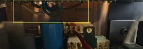
You can se these wires are soldered to the back side of the driver board, marked with yellow rectangle.
I don't really know what the connectors in front of each driver board are for, but someone put two wires in there, I believe to facilitate measuring bias voltage from the top? Only a couple of small value e-caps replaced on each driver board, new muti-turn trimmers installed.
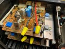
You can se these wires are soldered to the back side of the driver board, marked with yellow rectangle.
I don't really know what the connectors in front of each driver board are for, but someone put two wires in there, I believe to facilitate measuring bias voltage from the top? Only a couple of small value e-caps replaced on each driver board, new muti-turn trimmers installed.
Moving on to output transistors, I appears all have been replaced with new on-semi. I could only get a good picture of an MJ21194G, but assume the complement MJ21194G were used in the appropriate positions.
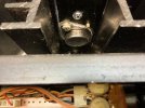
Also in the OT area, these red wires were cut off on both F-2497 boards. No idea why, and don't know what these should attach to. Is this a concern??
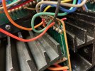
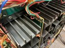
Looking at the filter caps, one has significantly bulged at the top (right in photo). Pressing on the top revealed it was firm, and not just warped plastic. Assume these should be replaced?
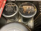
Also in the OT area, these red wires were cut off on both F-2497 boards. No idea why, and don't know what these should attach to. Is this a concern??
Looking at the filter caps, one has significantly bulged at the top (right in photo). Pressing on the top revealed it was firm, and not just warped plastic. Assume these should be replaced?
Finally, pre-amp appears to be untouched, all original. Lots of 2SA726 and 2SC1313 transistors in here along with old caps, diodes, etc.
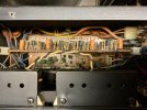
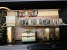
So, looking for opinions on the state of this amp. I'm demoing it to see if I want to purchase it from the seller. I suspected there were some issues based on the heat it gives off even at idle - not hot, but definitely medium-warm to the touch on the case above the PS board. What might be the cause of that? Other issues that might be red flags? Were I to purchase, it would be with the intent of doing a restoration, so I know I'm in for a fair amount of time and expense. However, on the positive side all OTs have already been replaced. Thanks for any opinions!
So, looking for opinions on the state of this amp. I'm demoing it to see if I want to purchase it from the seller. I suspected there were some issues based on the heat it gives off even at idle - not hot, but definitely medium-warm to the touch on the case above the PS board. What might be the cause of that? Other issues that might be red flags? Were I to purchase, it would be with the intent of doing a restoration, so I know I'm in for a fair amount of time and expense. However, on the positive side all OTs have already been replaced. Thanks for any opinions!

The use of wire nuts indicates to me that either the person that did the work was thinking that was a temporary fix or test set-up. OR, they didn't know what they were doing in general. However, if the unit plays and sounds anywhere near decent, then no damage was done most likely.
It sounds good, though I can't say it sounds any better than my AU-9900, which has been restored. I realize I would be buying this for the satisfaction of owning an AU-20000 more than that it sounds better than my other Sansui gear (in my signature).How does it sound and is the price reasonable given the average condition it appears to be in?
Can't discuss price here. I'll probably post a thread in Dollars and Sense to see what people think.


You probably know in your gut if it is reasonable priced or not given the premium these can bring. Really wasn't expecting a number.
Not a direct comparison but I had a mint set of BA / CA 2000 and they did not sound as good as my AU-9900A. All of these were in beautiful cosmetic shape and in original, unrestored condition. While the BA 2000 meters were pretty to look at, the AU-9900A sounded better to my ears and the BA / CA combo was sold. Maybe a restoration would have changed my mind, but no sense in looking back.
Not a direct comparison but I had a mint set of BA / CA 2000 and they did not sound as good as my AU-9900A. All of these were in beautiful cosmetic shape and in original, unrestored condition. While the BA 2000 meters were pretty to look at, the AU-9900A sounded better to my ears and the BA / CA combo was sold. Maybe a restoration would have changed my mind, but no sense in looking back.

What's been done counts as 'Serviced' in some people's eyes, most concerning for me would be those cut wires, the nasty looking solder joints, and the casual scattered component replacements.
I've always liked to look of the AU-20000 and the huge reserves of power, although they are not particularly exceptional in sonic terms from what I have read. I have never owned one or had one to repair, so I can't speak from personal experience.
I've always liked to look of the AU-20000 and the huge reserves of power, although they are not particularly exceptional in sonic terms from what I have read. I have never owned one or had one to repair, so I can't speak from personal experience.
Agree with your sentiments. Need to find out where those cut wires were connected to. Sharp eye on the solder joints, I forgot to mention that. I saw quite a few connections that looked poor.What's been done counts as 'Serviced' in some people's eyes, most concerning for me would be those cut wires, the nasty looking solder joints, and the casual scattered component replacements.
I've always liked to look of the AU-20000 and the huge reserves of power, although they are not particularly exceptional in sonic terms from what I have read. I have never owned one or had one to repair, so I can't speak from personal experience.

Nice esthetics, shoddy work but nothing catastrophic. Fun project, I would get it.

DB-7
Super Member
From a Sansui collector item view point, I would definitely find a way to grab it.
The AU-20000 are very rare and those that do have them don't offer them forsale very often.
I almost had one a few weeks ago but the owner went a different way with it.
It is complete, working and in decent condition. Any short comings of the internals are easily addressed imo.
The AU-20000 are very rare and those that do have them don't offer them forsale very often.
I almost had one a few weeks ago but the owner went a different way with it.
It is complete, working and in decent condition. Any short comings of the internals are easily addressed imo.

You probably know in your gut if it is reasonable priced or not given the premium these can bring. Really wasn't expecting a number.
Not a direct comparison but I had a mint set of BA / CA 2000 and they did not sound as good as my AU-9900A. All of these were in beautiful cosmetic shape and in original, unrestored condition. While the BA 2000 meters were pretty to look at, the AU-9900A sounded better to my ears and the BA / CA combo was sold. Maybe a restoration would have changed my mind, but no sense in looking back.
From what I recall, the BA/CA2000 share many internals with the AU-11000A/AU-9900A, so likely just condition affected the SQ.
The AU-22000 is a different beast, not sure how much similarity in topology.
Agree, BA/CA-2000 are just an AU-11000A in separate boxes (and with meters). AU-20000 is most similar to BA/CA-3000.From what I recall, the BA/CA2000 share many internals with the AU-11000A/AU-9900A, so likely just condition affected the SQ.
The AU-22000 is a different beast, not sure how much similarity in topology.
Put this board comparison together a while ago for the Definition and Professional series.

I was not trying to imply there are any similarities between the AU-20000 and the BA/CA 2000, just an agreement about how good the AU-9900A sounds. From a collectors stand point I probably should have kept the BA/CA 2000 combination as they were exceptionally clean, with boxes, and probably will never find another pair for what I paid for them. We just can't keep everything. Or can we? 
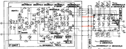
Investigated the cut red wires. They are connected to points 2 and 4 on F-2497. These should connect to points 2 and 4, respectively on board F-2510, though not sure where that is in the unit. Looks like that is just a pass through board to the driver boards. Points 2 and 4 connect to the base of TR06 and TR07, respectively, on F-2507 through a couple of diodes. Should these be re-attached? What might be the reason they were cut?

richardpp
Well-Known Member
The wires running between the driver board F-2507 and F-2512 were originally done at the factory to make a more reliable connection between the driver board and the bias transistor located on F-2497 as well as for the signal and feedback connections. Gray (e), blue (c) and green (b), brown signal and white feedback. You can see those wires in Kale's restoration pics. I had the same wires on mine as well. They're not easy to remake once the driver board has been removed, hence the mess. Omitting the connector board F-2510 (as was used in the BA-3000) and soldering the wires directly to the board was also, I guess, a means to shore up the integrity of the connections between the driver board and the output board. Hence the empty connector block. However, it was used in later production.
The extra wires that have been cut off or capped have been added to facilitate bias adjustments and obviously should be removed. Connections 2 and 4 are the bias test points going to the emitter resisters on the output board. (TR06 and TR07 and diodes D08 and D09 on the driver board are for current limiting.)
Heat from the regulated power supply board is due to the large voltage drop required for the 35V preamp supply. In later versions, the voltage dropping resistors were relocated to the underside of the amp and their power rating (and physical size) increased to 15W but even then they struggle to dissipate the heat effectively. Some owners have fitted chassis-mounted aluminium-cased resistors to alleviate the issue. You are right not to force removal of this board, the clip on the connector needs to be held back at the same time as pulling the board out. That clip is tight!
The main filter caps sleeves have definitely shrunk back. I found Nichicon KG Gold Tune to be a perfect replacement, alternatively KG Super Through.
This looks like an earlier version of the AU-20000. Later production located the bias transistor on the driver board. Cosmetically, it looks very nice. It has all the original knobs. I notice some of the chassis screws have been replaced, the original ones were black. For reliability, the output board pass-throughs need to be fixed. Otherwise, the work done to the amp looks superficial and would be dealt with quickly during your restoration process. The amplifier itself is a master of integration, boards are accessible and everything is laid out well. Good luck.
Edited for clarification: "Omitting the connector block ...." was changed to "Omitting the connector board F-2510 ..."
The extra wires that have been cut off or capped have been added to facilitate bias adjustments and obviously should be removed. Connections 2 and 4 are the bias test points going to the emitter resisters on the output board. (TR06 and TR07 and diodes D08 and D09 on the driver board are for current limiting.)
Heat from the regulated power supply board is due to the large voltage drop required for the 35V preamp supply. In later versions, the voltage dropping resistors were relocated to the underside of the amp and their power rating (and physical size) increased to 15W but even then they struggle to dissipate the heat effectively. Some owners have fitted chassis-mounted aluminium-cased resistors to alleviate the issue. You are right not to force removal of this board, the clip on the connector needs to be held back at the same time as pulling the board out. That clip is tight!
The main filter caps sleeves have definitely shrunk back. I found Nichicon KG Gold Tune to be a perfect replacement, alternatively KG Super Through.
This looks like an earlier version of the AU-20000. Later production located the bias transistor on the driver board. Cosmetically, it looks very nice. It has all the original knobs. I notice some of the chassis screws have been replaced, the original ones were black. For reliability, the output board pass-throughs need to be fixed. Otherwise, the work done to the amp looks superficial and would be dealt with quickly during your restoration process. The amplifier itself is a master of integration, boards are accessible and everything is laid out well. Good luck.
Edited for clarification: "Omitting the connector block ...." was changed to "Omitting the connector board F-2510 ..."
Last edited:
Thanks for all that great info and insights! That greatly helped me understand what's going on with the driver boards, PS, and wires on F-2497. As you state, the unit I have here is missing F-2510 connector boards, and wires from F-2497 are soldered to the connector pins on F-2512. Looks like in Kale's thread he had. a couple F-2510 connectors, as they appear in his final assembly in the amp.The wires running between the driver board F-2507 and F-2512 were originally done at the factory to make a more reliable connection between the driver board and the bias transistor located on F-2497 as well as for the signal and feedback connections. Gray (e), blue (c) and green (b), brown signal and white feedback. You can see those wires in Kale's restoration pics. I had the same wires on mine as well. They're not easy to remake once the driver board has been removed, hence the mess. Omitting the connector board F-2510 (as was used in the BA-3000) and soldering the wires directly to the board was also, I guess, a means to shore up the integrity of the connections between the driver board and the output board. Hence the empty connector block. However, it was used in later production.
The added complication on this unit is someone soldered wires from the solder pads on F-2512 for the F-2510 connectors directly to the driver board on the foil side. The wires are passed through the square hole between the driver board connectors on F-2512. I've marked those areas with yellow arrows in the picture below.
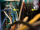
Looks like the five wire colors/signals you mentioned are the ones fed through. The picture below is not too bright, but you can see the five wires soldered to the back of the driver board (area in yellow square.)
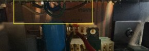
I can only assume some previous "tech" thought there was a bad connection at the driver board pins, and so soldered wires directly to the driver boards. I believe the current owner replaced some capacitors on the driver boards, so he would have had to de-solder and then re-solder those "bypass" wires to get the driver boards out. If I purchase this amp, those will all come out and pin connections checked for good contact.
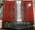
Interesting about the PS board dropping resistors. That is definitely the area that gets warm on the top cover. There's really no facility for air circulation in the driver board/PS area. Just slots in the cover over the area, but not in the top cover over this area!
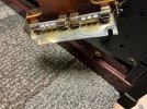
Just noticed the four feet have all been replaced with smaller ones.