

You are using an out of date browser. It may not display this or other websites correctly.
You should upgrade or use an alternative browser.
You should upgrade or use an alternative browser.
Opinions on state of AU-20000 sought
- Thread starter KeithD
- Start date
-
- Tags
- sansui au-20000

richardpp
Well-Known Member
Yes, that's correct.It looks like the covers on the AU-20000 are held on by ordinary Black M3x8 coarse thread screws. The same type of screw that holds the chassis together.

DEFTECHY
Well-Known Member
Completed the acquisition today. Any recommendation for where to get the correct "light green" lamps for the meters?
@LBPete sells replacement feet, so I'll be getting a set of those. Also need to source correct black screws for the case. I count at least 7 non-original screws, some of which are not really the correct size.
Congrats on the AU20k. Looks like a nice unit from the pics. Looking forward to a restoration thread.
richardpp
Well-Known Member
@KeithD, I just noticed the black chassis screws holding down the heatsink brackets in your photo from post #4. I think someone has got the screws mixed up. The gold passivated screws with the flange are meant for the heatsinks (x8). In some places they are also used for pcb ground connections. The black chassis screws are used everywhere else, including for attaching the top, bottom and side covers. Hope I haven't caused you an unnecessary expense here.


Interesting, I'll take a closer look at that. There were a few other non-original screws, I think, but given that the output transistors were all replaced, I can see how someone got the screws mixed up if they did not pay attention. I needed to order replacement feet from Pete and he had replacements screws, so I just added them to the order. Good to have spares anyway.@KeithD, I just noticed the black chassis screws holding down the heatsink brackets in your photo from post #4. I think someone has got the screws mixed up. The gold passivated screws with the flange are meant for the heatsinks (x8). In some places they are also used for pcb ground connections. The black chassis screws are used everywhere else, including for attaching the top, bottom and side covers. Hope I haven't caused you an unnecessary expense here.
View attachment 3781304
The item I'm looking for now is good replacements for the filter caps. Mouser and Digikey no longer have the Nichicon ones you recommended. Looks like some are using Chemi-con.
Turns out those 8 screws were present, just in different locations! So, I moved all but one to the correct locations holding the heatsink brackets in place. One had been replaced with a larger screw, so the original no longer threads in.@KeithD, I just noticed the black chassis screws holding down the heatsink brackets in your photo from post #4. I think someone has got the screws mixed up. The gold passivated screws with the flange are meant for the heatsinks (x8). In some places they are also used for pcb ground connections. The black chassis screws are used everywhere else, including for attaching the top, bottom and side covers. Hope I haven't caused you an unnecessary expense here.
View attachment 3781304
Also, pulled out the PS board. Previous owner had screwed pieces of aluminum onto the heatsinks for TR11 and TR16.
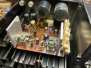
Removed those and cleaned up the excessive thermal paste.


Looks like diodes were not replaced, glue not cleaned up. Capacitors look like a mixed bag of types and quality. I'm thinking I should pull all the capacitors and start over. Need to clean the glue off and replace known problematic diodes (D01, 02). Anyone seeing anything else that should be replaced?

ConradH
Lunatic Member
With enough alcohol and a couple toothbrushes it should clean up nicely. What are those two fragile looking red things near the corner? Thermistors? Be careful cleaning there. I'd replace the caps both for appearance's sake and to see if a better job can be done with the glue removal. I wonder if it runs hot enough to justify adding those two aluminum plates?
Those are D01, 02 Varistors (VD1212) and should be replaced with 2x 1N4148.What are those two fragile looking red things near the corner? Thermistors?
It does get warm over the large resistors, which is typical for this design from what @richardpp stated earlier in the thread. My concern with the large pieces of aluminum added is that it may restrict what little air flow there is around the large resistors. I don't think TR11 &16 are what's causing most of the heat.
richardpp
Well-Known Member
some measurements might help:
Power dissipated by the D382 transistor = 2.6W
where C-E voltage is 22.4V
and collector current is 0.117A
Power dissipated by the two 220Ω resistor (arrays) combined = 6W.
where the voltage drop across each 220Ω resistor = 25.8V.
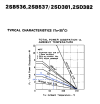
The resistors account for more heat but that heat decreases the amount of power the D382 transistor can safely dissipate. I marked this on the data sheet below. The heatsink is roughly 6cm x 2.5 cm, approx. 15cm2 and the power dissipation of the transistor is 2.6W (idle). This tells us that approx. 65ºC ambient is about as much as the transistor is intended to handle.
The older style pcb boards I've noticed are often (or always) heavily darkened in that area. TR16, on the other side of the board and well away from the heat, gets a much easier life. Relocating the power resistors as Sansui did seems to have made a difference. The boards I have don't show the same signs of heat. Going by serial numbers, both of our amps are 1975 production so I guess the problem was rectified in a relatively short time frame. I've added a couple of photos to show the change Sansui made in relocating the resistors, you might have seen this already, and a photo from the web that shows how someone else (credit to them) relocated the resistors to an adjacent side panel.
The heatsinks for TR11 and TR16 are potentially live because the collector is not insulated. The extra material increases the risk of contact with 60-70Vdc which may be another reason to leave them out.
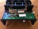
Two 15W cement resistors replace 2 x (150Ω + 120Ω /1.2KΩ) resistors. The connector underneath plugs into F-2508.
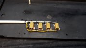
Chassis mount.
Hope this helps
Power dissipated by the D382 transistor = 2.6W
where C-E voltage is 22.4V
and collector current is 0.117A
Power dissipated by the two 220Ω resistor (arrays) combined = 6W.
where the voltage drop across each 220Ω resistor = 25.8V.
The resistors account for more heat but that heat decreases the amount of power the D382 transistor can safely dissipate. I marked this on the data sheet below. The heatsink is roughly 6cm x 2.5 cm, approx. 15cm2 and the power dissipation of the transistor is 2.6W (idle). This tells us that approx. 65ºC ambient is about as much as the transistor is intended to handle.
The older style pcb boards I've noticed are often (or always) heavily darkened in that area. TR16, on the other side of the board and well away from the heat, gets a much easier life. Relocating the power resistors as Sansui did seems to have made a difference. The boards I have don't show the same signs of heat. Going by serial numbers, both of our amps are 1975 production so I guess the problem was rectified in a relatively short time frame. I've added a couple of photos to show the change Sansui made in relocating the resistors, you might have seen this already, and a photo from the web that shows how someone else (credit to them) relocated the resistors to an adjacent side panel.
The heatsinks for TR11 and TR16 are potentially live because the collector is not insulated. The extra material increases the risk of contact with 60-70Vdc which may be another reason to leave them out.
Two 15W cement resistors replace 2 x (150Ω + 120Ω /1.2KΩ) resistors. The connector underneath plugs into F-2508.
Chassis mount.
Hope this helps
Last edited:
Thanks for those insights and pictures @richardpp ! Interesting that they moved those resistors to under F-2512, and that it was done fairly early in production. I've gone through the thread by @w1jim restoring a very early 20000 (October '75). That one looks very much like mine. He also moved the PS resistors to a location on the case. Here's a picture from his thread showing them mounted.some measurements might help:
Power dissipated by the D382 transistor = 2.6W
where C-E voltage is 22.4V
and collector current is 0.117A
Power dissipated by the two 220Ω resistor (arrays) combined = 6W.
where the voltage drop across each 220Ω resistor = 25.8V.
The resistors account for more heat but that heat decreases the amount of power the D382 transistor can safely dissipate. I marked this on the data sheet below. The heatsink is roughly 6cm x 2.5 cm, approx. 15cm2 and the power dissipation of the transistor is 2.6W (idle). This tells us that approx. 65ºC ambient is about as much as the transistor is intended to handle.
The older style pcb boards I've noticed are often (or always) heavily darkened in that area. TR16, on the other side of the board and well away from the heat, gets a much easier life. Relocating the power resistors as Sansui did seems to have made a difference. The boards I have don't show the same signs of heat. Going by serial numbers, both of our amps are 1975 production so I guess the problem was rectified in a relatively short time frame. I've added a couple of photos to show the change Sansui made in relocating the resistors, you might have seen this already, and a photo from the web that shows how someone else (credit to them) relocated the resistors to an adjacent side panel.
The heatsinks for TR11 and TR16 are potentially live because the collector is not insulated. The extra material increases the risk of contact with 60-70Vdc which may be another reason to leave them out.
View attachment 3784349
View attachment 3784404
Two 15W cement resistors replace 2 x (150Ω + 120Ω /1.2KΩ) resistors. The connector underneath plugs into F-2508.
View attachment 3784405
Chassis mount.
Hope this helps

I think that is a very good long term solution. For some heat relief, it seems the PS resistors could be pulled up a bit and angled away from the heatsink for TR11 on the PS board in my unit. I also wondered about mounting new ones well off the board vs. mounting and wiring a Molex connector. For whatever reason, in Kale's write-up of the restoration of an early 20000, he left those resistors in place.
richardpp
Well-Known Member
I also wondered about mounting new ones well off the board vs. mounting and wiring a Molex connector.
I think that's a good idea! A little more airflow around the resistors could make a big difference.
Nice to keep the amp looking original but still improved!
Last edited:
Parts arrived yesterday (Mouser was very slow on this order for some reason). Will start on the PS board soon. Went with Panasonic caps for the most part as Nichicon appears to no longer make many of the values needed for vintage gear. Planning to work board by board and test on DBT, but then I was wondering if I need a larger wattage bulb to use with the 20000. Any suggestions on value? Not sure how high a wattage I can get anymore, so might need to have 2 or 3 in series.

You want a LOWER wattage bulb, 60 watt should work. The higher the wattage of the bulb, the lower it's resistance. You want more resistance not less. Also keep in mind that the protection circuit may interpret the lower voltage caused by the DBT as a short and trigger the protection circuit. The DBT will still work and you can do whatever testing you need to do.
- Pete
- Pete
Started working on the PS board. Removed all e-caps, small signal transistors, diodes, and resistors affected by glue. Removed glue residue and installed new diodes.
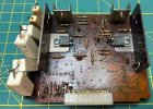
Have yet to make a decision on the dropping resistors before I order parts. Mount new ones well off the board, or put a connector on the board and use surface mount resistors to mount on the side panel. The surface mount ones are probably the wisest option for maximum heat dissipation. In either case, anyone have a recommendation for wattage? I've seen 15 - 25 watt resistors used in other threads. Originals are 5W.
Have yet to make a decision on the dropping resistors before I order parts. Mount new ones well off the board, or put a connector on the board and use surface mount resistors to mount on the side panel. The surface mount ones are probably the wisest option for maximum heat dissipation. In either case, anyone have a recommendation for wattage? I've seen 15 - 25 watt resistors used in other threads. Originals are 5W.

Of course it's ok to use higher wattage resistors, but at some point their size comes into play. If it were me I might make a small increase to their wattage, to 10w for example. Obviously when replacing two with one, you'll need to add the power ratings together, so 10w (or 15w) for 5+5w makes good sense. 
The higher wattage replacements will just have a slightly easier life. While still dissipating the same amount of heat as the originals.
The higher wattage replacements will just have a slightly easier life. While still dissipating the same amount of heat as the originals.
Last edited:
Thanks for the input, John. I ordered 25W surface mount resistors. I think they will work well. They were about the same price and not much larger than 15W ones.Of course it's ok to use higher wattage resistors, but at some point their size comes into play. If it were me I might make a small increase to their wattage, to 10w for example. Obviously when replacing two with one, you'll need to add the power ratings together, so 10w (or 15w) for 5+5w makes good sense.
The higher wattage replacements will just have a slightly easier life. While still dissipating the same amount of heat as the originals.
Made progress on the PS board, recapped with Panasonic FC series caps, replaced all small signal transistors, 4 diodes replaced. Replaced dropping resistors with surface ones mounted on the sidewall. I re-used the two aluminum blocks the previous owner mounted on the transistor heat sinks, by putting them between the resistors and the sidewall as additional heat sink material.
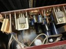
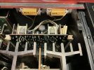
I let it idle for about 1/2 hour before setting bias and DC offset. Sounding great. Next will be tackling the two driver boards.
I let it idle for about 1/2 hour before setting bias and DC offset. Sounding great. Next will be tackling the two driver boards.
Yes, this worked well, and was definitely the best solution for heat dissipation. Before starting work on the board I measured the temperature of one of the original dropping resistors after about 15 minutes of idle. I measured 80 ºC and rising at the resistor surface. I played the amp for a couple of hours yesterday then measured temperature at the surface of the new resistors and got just under 50 ºC. The top over the PS and the right side were definitely warm to the touch, but that's energy that is not being placed inside the PS/driver board area. I'd like it if that area were cooler, but I believe this is the nature of the amp design.Nice work! The new resistors look good, are you happy with the change?
I should add that I did think about and explore other options for heat dissipation before mounting the new resistors. Seems to me the issue with heat dissipation in this area of the amp is that no facility was designed in for it. I find this unusual for Sansui. In my limited experience with other Sansui amps/receivers, I feel Sansui gave due consideration to dissipating the heat generated by various parts of the amps. However, not so with the AU-20000. I'm assuming the BA-3000 has the same issue, since the amp section appears identical. There is no venting for air to move from the underside of the case to the top in the area of the PS/driver boards. There are slots in the shielding above these boards, but curiously, no slots in the outer case directly above this area.
I thought about various ways to remedy this. F-2512 covers the entire bottom of the area with the PS and driver boards, so there is really no way to increase venting from the bottom. I have some spare parts from vintage computers, and I tried placing an old graphics card fan on the wall dividing the PS from the pre-amp section.
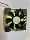
It will run on ~4 - 12 VDC. I powered it with ~6V from an external PS. This had a significant affect lowering the temperature in that area, and specifically the original dropping resistors. I think this is a viable option. The fan noise is very low and would not be heard over any music played by the amp. The transformer seems to have a 5.7V tap to power the meter lights, if I'm reading it right, so it would be a matter of tapping in to that to power the fan. Maybe that's a crazy idea, but if it worked, it would significantly reduce temperatures by introducing air movement. Any thoughts?
I thought about various ways to remedy this. F-2512 covers the entire bottom of the area with the PS and driver boards, so there is really no way to increase venting from the bottom. I have some spare parts from vintage computers, and I tried placing an old graphics card fan on the wall dividing the PS from the pre-amp section.
It will run on ~4 - 12 VDC. I powered it with ~6V from an external PS. This had a significant affect lowering the temperature in that area, and specifically the original dropping resistors. I think this is a viable option. The fan noise is very low and would not be heard over any music played by the amp. The transformer seems to have a 5.7V tap to power the meter lights, if I'm reading it right, so it would be a matter of tapping in to that to power the fan. Maybe that's a crazy idea, but if it worked, it would significantly reduce temperatures by introducing air movement. Any thoughts?


