• The move to the new server is done. There are some software and database maintenance updates in process. This has us passing the hat around to help out. We appreciate any donations. Seriously, even a dollar helps. The payment page may be found here - https://www.audiokarma.org/support.html

Opinions on state of AU-20000 sought

The excess heat, in my opinion, comes from poorly chosen transformer secondary voltages. Maybe there was an electronics design change which then made the transformer voltages too high? But they knew they could get around the issue with dropper resistors. And maybe with the AU-20000 being such a powerful amplifier, people wouldn't notice the heat. Another possibility is a mistake when Sansui originally ordered the transformers?

The AU-D11 II voltages must be perfect because the amplifier always runs as cool as a cucumber. ;)
 
Last edited:
The excess heat, in my opinion, comes from poorly chosen transformer secondary voltages. Maybe there was an electronics design change which then made the transformer voltages too high? But they knew they could get around the issue with dropper resistors. And maybe with the AU-20000 being such a powerful amplifier, people wouldn't notice the heat. Another possibility is a mistake when Sansui originally ordered the transformers?

The AU-D11 II voltages must be perfect because the amplifier always runs as cool as a cucumber. ;)
AU-9900 is the same, cool as a cucumber.

I think you are right about the choices of voltages from the transformer. The 20000 has 85 V supplied to the PS board and then dropping that to 65 and 35 V. The drop to 35 V is the source of most of the heat at the resistors. Guess that design made more sense to them than sourcing a second voltage off the transformer. Also, three resistors are used to make that drop, so they may have felt that was enough for good heat dissipation. However, given that choice, I'm still surprised they did not design for better air circulation to cool those resistors. :dunno:
 
Last edited:
IMHO the real issue isn't so much the heat from the original dropping resistors but that they were placed on the PS board and effectively fried it.
Placing (larger) resistors away from the board is the proper workaround.
I'm surprised Sansui didn't figure out the flaw in their original design. I think later versions made an effort to move the resistors further away.
Like any product - simple things like this can be their downfall.
 
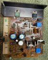
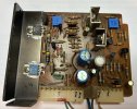
Started work on the left driver board. Previous owner replaced 4 of 5 e-caps, but again with a mixed bag of capacitors. Couple of "Lelon" caps. Doing a search, seems these are Chinese caps rated at 85 ºC. Glue was not removed.

IMG_3636.jpeg

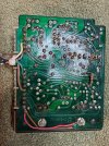
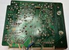
Looking at the back of the board, looks like and entire trace from TR10 to the connector pin suffered damage. Of course, we also have the 5 wires duplicating connections to F-2512.

IMG_3637.jpeg

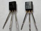
TR01/02 were also replaced with these. Previous owner tends to favor NTE transistors, so I assume that's what these are?

IMG_3642.jpeg

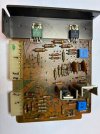
Removed all e-caps, small signal transistors and diodes, and cleaned off glue residue. Here's the board with new D01-03 installed.

IMG_3643.jpeg

Will test after the board is done, then move on to the right driver board.
 
C1775 are 2SC1775 - not NTE.
The Lelon capacitors were probably indicative of a commercial shop doing the work.
Those are probably decent caps that they can buy cheap in large quantities. Buy them for a dime each and sell them for $2.50.
That's the kind of thing a commercial shop needs to do to lower overhead and survive.

Most DIY hobbyists will buy the better quality capacitors since the price difference is not significant.
 
Much progress today. Finished and tested the L driver board, all good. So, worked on the R driver board. This one also had damage from previous work. Also, looks like someone tried cleaning the foil side with a wire brush. Lots of brush-like scratch marks on the green coating and solder joints. I can only shake my head. :rolleyes::no:

025C070D-92B5-4E6C-96C1-7F0D6F44DDE7_1_102_a.jpeg

98E25DD7-7F9B-4FA3-AFB2-13831925005C_1_102_a.jpeg

Can also see the solder pad is missing at the pin connected to the blue wire, so the wire was soldered to the trace.

This board got the same treatment as the Left board. I took a capacitor cutoff wire, bent a loop to go around the pin with the damaged pad, and solder that to the trace to reinforce the connection. I removed the 5 wires soldered to the back of the boards.

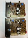
Both boards completed, reinstalled, offset and bias set after about 1/2 hour idle. Playing beautifully!

849149E3-7EF4-45E8-9FD7-1EDF583AC9C3_1_102_o.jpeg
 
I should add that I did think about and explore other options for heat dissipation before mounting the new resistors. Seems to me the issue with heat dissipation in this area of the amp is that no facility was designed in for it. I find this unusual for Sansui. In my limited experience with other Sansui amps/receivers, I feel Sansui gave due consideration to dissipating the heat generated by various parts of the amps. However, not so with the AU-20000. I'm assuming the BA-3000 has the same issue, since the amp section appears identical. There is no venting for air to move from the underside of the case to the top in the area of the PS/driver boards. There are slots in the shielding above these boards, but curiously, no slots in the outer case directly above this area.

I thought about various ways to remedy this. F-2512 covers the entire bottom of the area with the PS and driver boards, so there is really no way to increase venting from the bottom. I have some spare parts from vintage computers, and I tried placing an old graphics card fan on the wall dividing the PS from the pre-amp section.
A few late comments:

It sounds like your chassis mounted resistors are a significant improvement!

I agree with you that there isn't much ventilation in that area of the amp, however I think that a fan might be ineffective in such an enclosed space. Removing the baffle that shields the circuit boards from main heatsink might open up the space and allow more natural convection. I guess it's something you could try.

I don't have hands on experience with the BA-3000 but I suspect the 35V regulator in the AU-20000 runs substantially hotter due to its control amp section. The power section of the two models were not always the same. One of the hangovers of the early BA-3000 design is the published bias current spec of 20mA, significantly lower than that of the AU-20000.

Glad to hear that all is going well and I'm interested to see where you go next. It's a real shame those driver boards have been treated so roughly. How on earth someone fitted that heavy gauge blue wire through the hole in F-2512 is beyond me. I was also wanting to ask if the zener diodes at ZD01 were 22V or 24V?
 
The original Zeners are marked 2456R.
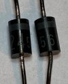
IMG_3655.jpeg

Does that indicate they are 24V? I'm not familiar with how these are marked to indicate their voltage. I used BZX55B22-TR for replacements, which are 22 V.

It does seem a lot of of the generated heat is now being dissipated by the side wall the resistors are mounted on as well as the outer side panel. After a couple hours of power on, the side panel is pretty warm along with the top over that area.

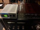
Being a scientist, I always want data, so I brought a temperature sensor home from the lab to do some temperature readings in the area of the PS. I've placed the sensor about 1/2 inch away from the two resistors hanging in the air, so I can get an idea how warm that area gets.
IMG_3656.jpeg

It's a bit hard to see, but the thermocouple wire is threaded through a vent opening in the top and in the shielding over the PS internally. I also fitted the graphics card fan on the wall separating the pre-amp from the PS, taking power from the meter light feed. Initial rough tests showed the fan does make a difference, but need to do a time vs. Temp study with the fan on and off from cold start. Will report back with results.

The last parts from my initial order are the two filter caps, so I will likely fit those in next. Meanwhile, I'll need to look at what's needed for the protection board to see if I'll need to make a new order.

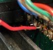
FYI, I believe I have determined that the "cut" wires on F-2497 referred to in post #4 were added when the OTs were replaced to aid in measuring the bias voltage. Taking a closer look at those wires, there is enough room on each to attach a micro-grabber for measurement with a DMM.
IMG_3652.jpeg

These two junctions are connected to pins 2 & 4 on F-2512. I think a previous tech determined that something needed to be added to measure voltage on those two pins, since this unit does not have the F-2510 connectors needed to attached the DMM leads. At first, I tried measuring points 2 & 4 holding the pointed ends of DMM test leads on the solder pads on F-2512, but of course that leaves one with no hands to adjust the VR! It becomes a matter of trial and error if one wants to follow that procedure. However, using the wires on the F-2497 boards works well.

 
I added the wires on mine with shielded connectors on the end. Otherwise, as you noted it's impossible to test the voltages and the risk of shorting something out is significantly decreased.

Mine, as I noted earlier is a very early version with the bias transistors mounted on the outputs instead of the drivers.
I'm lo longer able to do this kind of work but my tech reports progress redesigning the driver PCBs.
He's taken it on as a personal challenge.
 
Does that indicate they are 24V? I'm not familiar with how these are marked to indicate their voltage. I used BZX55B22-TR for replacements, which are 22 V.

Yes those are 24V Zener diodes. Thanks for that. I'm trying to piece together a timeline of production changes. The service manual lists a 22V Zener diode which suggests early manufacturing, circa 1975, might predate the manual.
 
Last edited:
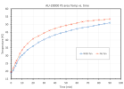
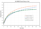
I recorded temperature approximately every 5 minutes yesterday for 90 minutes with the fan on, and today with the fan off. In both cases I was playing music through the amp at a typical volume level for my listening. Here is a plot of the data.

Screenshot 2026-07-20 at 5.21.32 AM.png

With no fan on the temperature increases faster, and settles at approximately 4 ºC higher than when the fan is on between about 20 to 70 minutes. Then the difference begins to narrow. I suspect at some point past 90 minutes a thermal equilibrium would be established and the temperature readings with and without the fan would merge on the same value. Also notice that the temperature increases at about the same rate in both scenarios. The rates decrease slowly with time. Pretty sure there would be a larger difference if the fan were positioned to introduce outside air to the PS area, but as it is, it's mostly just moving air around in the PS/driver board area.

I'm unsure if a 4 ºC lower temperature is worth the extra effort of the fan or not. In general, higher temperatures shorten the life of electronics components, I believe, but is a 4 ºC difference really significant? Food for thought.

@richardpp I think you are right that leaving the metal divider between the OT heat sinks and the PS/driver area would allow better air movement, but I'm assuming their was a reason for the shielding? Any thoughts?
 
Last edited:
I recorded temperature approximately every 5 minutes yesterday for 90 minutes with the fan on, and today with the fan off. In both cases I was playing music through the amp at a typical volume level for my listening. Here is a plot of the data.

View attachment 3804184

With no fan on the temperature increases faster, and settles at approximately 4 ºC higher than when the fan is on between about 20 to 70 minutes. Then the difference begins to narrow. I suspect at some point past 90 minutes a thermal equilibrium would be established and the temperature readings with and without the fan would merge on the same value. Also notice that the temperature increases at about the same rate in both scenarios. The rates decrease slowly with time. Pretty sure there would be a larger difference if the fan were positioned to introduce outside air to the PS area, but as it is, it's mostly just moving air around in the PS/driver board area.

I'm unsure if a 4 ºC lower temperature is worth the extra effort of the fan or not. In general, higher temperatures shorten the life of electronics components, I believe, but is a 4 ºC difference really significant? Food for thought.

@richardpp I think you are right that leaving the metal divider between the OT heat sinks and the PS/driver area would allow better air movement, but I'm assuming their was a reason for the shielding? Any thoughts?

Because of its enclosed nature I'd say the purpose of the baffle is to maintain that section of the amp at a stable operating temperature. The vents in the top of the baffle determine how much heat can escape as a basic way of regulating the temperature. The problem is that low voltage regulator in the AU-20000 generates more heat than the original design may have allowed for.

I tried your experiment for myself. I placed a thermocouple temp sensor in approximately the same position, top cover on, music playing at nominal listening level and monitored for an hour. Obviously it's not going to be exactly the same conditions as yours but despite that the results were surprisingly similar even though the large voltage dropping resistors in my unit are on the underside of F-2512. My take-away from this is that your chassis mount resistors are doing a very good job of dissipating power and what you're measuring must be residual heat from the transistors. I repeated the experiment with the baffle removed. This time the results were 5ºC to 7ºC lower over the range.

This is all guesswork, really.
 
Last edited:
Because of its enclosed nature I'd say the purpose of the baffle is to maintain that section of the amp at a stable operating temperature. The vents in the top of the baffle determine how much heat can escape as a basic way of regulating the temperature. The problem is that low voltage regulator in the AU-20000 generates more heat than the original design may have allowed for.

I tried your experiment for myself. I placed a thermocouple temp sensor in approximately the same position, top cover on, music playing at nominal listening level and monitored for an hour. Obviously it's not going to be exactly the same conditions as yours but despite that the results are surprisingly similar even though the large voltage dropping resistors in my unit are on the underside of F-2512. I repeated the experiment but this time with the baffle removed. The results were 5ºC to 7ºC lower over the range. My take-away from this is that your chassis mount resistors are doing a very good job of dissipating power and what you're measuring appears to be residual heat from the transistors.

This is all guesswork, really.
Thanks for that information Richard, very interesting results! I did wonder how temperature would be different in the later design with the dropping resistors on the bottom. of F-2512. Your opinion that the shield is mostly for regulating temperature makes sense. The SM calls for letting the amp run for 5 minutes before setting DC and bias, but I found values drifted until about 1/2 hour of run time. Maybe those boards were designed to run at ~50 ºC? :dunno: If that's the case, not much point to trying to keep the temperature lower, especially if the ultimate "equilibrium" temperature is the same (given enough time to reach it.) I think one takeaway from my plot above is time to reach a certain temperature. Having a fan in there just delays the time to reach a given temperature. For example, it takes about 25 minutes longer to reach 50 ºC with the fan on vs. off. With the shield off, those delay times will be even longer. On the other hand, maybe with the shield off the "equilibrium" temperature may be lower, which would help with component longevity.

Agree the resistor relocation is working well. Most of the energy is being dissipated by the case, which is a good thing. :thumbsup:
 
Final test data. I removed the shield over the PS/driver area and ran tests with and without the fan. Surprisingly, the fan made no difference with the shield off.

Screenshot 2026-07-21 at 4.22.29 PM.png
So, with no fan installed, the largest difference was about 6 ºC cooler without the shield. Also, the scenario without the shield leveled off at about 47 ºC, whereas the temperature was still rising with the shield in place without and with a fan.

For the scenario with the shield in place, having a small fan to move air in the PS/driver area does make a difference, but after about 35 minutes, lower temps are achieved with the shield removed regardless of having a fan installed.
 
A few things, in no particular order:

1. Did you restore the damaged green mask on the foil side of the boards where it was scraped off/damaged? Years ago, I never used to do so when doing repairs on rough boards. However, about 5 years ago my approach to damaged boards had evolved, and I started applying green coating to replace wherever it was missing.

I also generally use copper tape and punch set rivets to repair damaged and missing pads and traces now. Mostly for the purpose of improving the aesthetic quality of such a repair.

2. I'm surprised how little difference the fan made in keeping the temp down, at least until the shield/baffle was removed.

3. Was already clarified, but an NTE device will always have only an NTE proprietary part number stamped on it. Same with SK and ECG series parts from years back (though these are seldom seen anymore). Those small signal transistors were JEIA part numbers.

4. Seeing this ordeal makes me especially glad I opted to get the BA/CA-3000 combo years ago, over the AU-20000. At the time, I had both options available to me, and willingly spent more to do the pre/power amp setup. Not that the 20000 can't be made reliable, but reading this thread, I have more of a distaste for it now just on account of the thermal management issues the design of the 20000 present.

Good show saving this one, in any case.
 
@Sansuiman

1. No, did not put anything over the scratched areas of the green coating. Any suggestions what to use?

2. I think the main factor in the fan effectiveness is how it is oriented in the space. I'm using a small fan that came off an old graphics card. It's designed to sit on top of the GPU. The fan pulls air toward it and it is dispersed out the four sides, passing over an aluminum grill. So, in the PS/driver space in the AU-20000, it was pulling air toward the wall that separates that area from the pre-amp, then blowing it out in 4 directions, only one (up) directed out of the space. So, I saw this as just getting some air movement in there rather than providing cooling air from the outside, that would be optimal if it could be achieved.

4. A comparison between a BA-3000 and the amp section of the AU-20000 is intriguing. To my eyes, the amps are the same (same design, same boards) yet for some reason bias on the BA-3000 is set at 20mA (20 mV measurement), while the AU-20000 is set at 35mA (35 mV measurement). The wording on the service manual pages for setting bias in each unit is identical (down to misspellings!) except for the bias current. The only difference I can see is a difference in the value of the dropping resistors on the BA-3000 (330 Ω) vs. 220 Ω on the AU-20000. In @Leestereo 's restoration thread of a BA-3000, the dropping resistors are mounted on the PS board, but the original design only used a single 330Ω/5W resistor vs. a combination of 3 resistors on front and back of the board in the AU-20000. I assume the lower bias current setting in the BA-3000 leads to less heat generated, but it would be interesting to have some quantitative data. I know I'm missing something regarding what's happening with F-2508 in the two units. The schematic shows ±85V input to the board and ±65/±35V output from the board in both SM, so I'm not understanding why the difference in dropping resistors and bias settings. OT's are the same, power out put is the same.

I was initially quite reluctant to take this one on, but now that I have, it's been much more interesting than I expected, and I've expanded my knowledge of amps, which I always find enjoyable.
 
Last edited:
@KeithD

Green solder mask coating should be available from the usual suspects (mouser, digikey). I know some techs use green nail polish, which I suppose works ok, but I use the genuine article. Stuff I'm using came from a local supplier that has since closed up shop.

Interesting your observations on the slight variations in BA-3000 versus AU-20000, particularly on the bias current spec. I've not had a 20000 here at any point, so have never peeked under the hood of one. I'm hard pressed to explain why they increased the bias current so much on the 20000.
 
Back
Top Bottom