• The move to the new server is done. There are some software and database maintenance updates in process. This has us passing the hat around to help out. We appreciate any donations. Seriously, even a dollar helps. The payment page may be found here - https://www.audiokarma.org/support.html

Opinions on state of AU-20000 sought

That's an extraordinary level of detailed knowledge displayed there. :bowdown:

Someone doing a restore on another one of these added 'in-line' main rail fuses, (x4 IIRC) as there was no protection otherwise from that 'track damage' problem/possibility.
Thanks John, a lot about a little :) I'm glad it's useful! I seem to recall it was a must fix thread by Transfrmr who first installed those fuses ... here it is; https://audiokarma.org/forums/threa...blems-and-must-fix-for-safe-operation.733713/
 
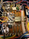
Removed TR01-5 and the small wattage resistors. Many of the resistors were out of spec (high by >10%); however, in the process of replacing the resistors, I discovered I somehow did not order replacements for three of the values, so I'll need to do another parts order. I replaced the values I had on hand with metal film/oxide types. Replaced TR01-5 with KSC1815Y.

I was wondering about the diodes. I see some replace them while others leave them. Anyone have thoughts?

5C669618-FA70-4A3C-9A5E-EEAE3EFC10A3_1_201_a.jpeg
 
Anyone have thoughts?

I would sometimes replace glass bodied diodes I thought were too tightly installed. I just thought they were so tight, the action of heating/cooling or mechanical disturbance (board flexing) might crack them. I would very often change Zeners for tighter tolerance (2%) types, and mount them above the pcb by ~1/4" or so, for heat shedding reasons.
 
Last edited:
I would sometimes replace glass bodied diodes I thought were too tightly installed. I just thought they were so tight, the action of heating/cooling or mechanical disturbance (board flexing) might crack them. I would very often change Zeners for tighter tolerance (2%) types, and mount them above the pcb by ~1/4" or so, for heat shedding reasons.
Thanks for those insights, John. I'll leave the diodes.

Repopulated the board with resistors I had on hand, transistors and capacitors. Just placed an order for the three resistor values I didn't have. So, completing the board will wait for those to come in. Plan to pick up some in-line fuse holders to put fuses on the rail power lines.

IMG_3806.jpegIMG_3805.jpeg

I hesitated on replacing R24 as it tested good, though I still might. I've got MFR50SFTE52-1K8 (1.8 kΩ, 1/2W) on hand, but it just looks so much smaller than the original. Maybe that's normal for metal film resistors? Also have RS02B6K800FE12 (6.8 kΩ, 3W) for R03 and 04, which some have listed as an upgrade for R03 and 04 (3.9 kΩ, 2W). I've noticed some replace R03, 04 and some do not. Any thoughts? Again, these replacements are smaller than the originals, but I assume they'll do the job just fine. If I put them in, I'll mount them with good clearance above the board.
 
Thanks for those insights, John. I'll leave the diodes.
The factory fit of the diodes in your PSU covers the 'tightness' issue. :thumbsup:

I hesitated on replacing R24 as it tested good, though I still might. I've got MFR50SFTE52-1K8 (1.8 kΩ, 1/2W) on hand, but it just looks so much smaller than the original. Maybe that's normal for metal film resistors?
It is normal, and I also distrust replacement resistors when they are really small, but this is only for the power LED so I can't think that it matters very much, except to wonder why they chose a carbon composition resistor in the first place. (cheapness and availability?)

Also have RS02B6K800FE12 (6.8 kΩ, 3W) for R03 and 04, which some have listed as an upgrade for R03 and 04 (3.9 kΩ, 2W). I've noticed some replace R03, 04 and some do not. Any thoughts? Again, these replacements are smaller than the originals, but I assume they'll do the job just fine. If I put them in, I'll mount them with good clearance above the board.
I assume the increase in value for these 3.9KΩ resistors is to reduce the current, as they are bleed resistors for the main PSU capacitors. And 3.9KΩ might be considered unnecessarily low in value for this function, and would reduce the heat they produce if increased in value, while still performing their function.
 
Last edited:
Actually, I'm noticing that the unit is coming out of protection a little faster than before restoration of the protection board resulting in a DC spike and pop in the speakers when the speaker relay clicks in. Any suggestions?
 
Nice work Keith! I like your choice of resistors for R03/4.

Re the time delay, I'm not sure why that would be but if you have a 24Vdc supply and the board is on the bench then you can run the speaker relay on its own. It's much easier to try different component values and monitor the delay when not having to reinstall the board each time. You'll need to bridge the posistor terminals 24 + 25 and 26 + 27 for it to work.

The only suggestions I have are to check resistors values especially R15 and R18,19, 20 or try a different transistor at TR04, KSC945 works there as well.

Edit, the old carbon comps might have given you a different time to the new metal films. What is your actual delay time?
 
Last edited:
The delay shouldn't change that much, or at all, if just changing resistor 'types', now values... that's a different thing. ;)
Agree, I did test each new metal film resistor before I put them in, just to be safe. Many of the old carbon ones were well out of spec.

Is this circuit just a time delay, and not sensing DC output? Was thinking the circuit detected DC and did not engage the relay until the DC got below some threshold value. I'll check the resistors, just in case I put something in wrong.

Will also check the old transistors to see what the gain is, though I did not keep track of which was TR04. I'll see if I can find a better match.
 
Very short, about 1-2 seconds. Previously it was more like 5 seconds or so.
Something is definitely not right there.

The circuit delays the speaker relay from closing to give the DC voltages time to settle.

If the transistor was the original one it would have been 2SC1364 and they can have relatively high gain, but I don't think that would cause such a big difference.
 
Last edited:
Something is definitely not right there.

The circuit delays the speaker relay from closing to give the DC voltages time to settle.

If the transistor was the original one it would have been 2SC1364 and they can have relatively high gain, but I don't think that would cause such a big difference.
Agree, something is not right.

Four of the five were original transistors (2SC1364) with black legs. One had been replaced at some point with a newer 2SC1364.

Won't be able to re-check components until later today or this weekend. I would say even the "first" relay click is faster - almost instantaneous with power on. That used to click in after about a second, and the second relay after 5 seconds or so, as I mentioned. So, both appear to be clicking in faster.

Would checking collector of TR04 to C07 (marked as 1V on schematic) tell us anything?

I'd guess the old caps had high ESR contributing to the delay, but not seeing much for caps in this circuit - just C905 and C07. Could one of those be contributing?
 
Re the time delay, I'm not sure why that would be but if you have a 24Vdc supply and the board is on the bench then you can run the speaker relay on its own. It's much easier to try different component values and monitor the delay when not having to reinstall the board each time. You'll need to bridge the posistor terminals 24 + 25 and 26 + 27 for it to work.
I do have a variable DC power supply. Do I just need to connected that to pin 12 & ground (along with the bridges you mentioned) for the circuit to work? It's a great solution vs. taking that board in and out - not fun! :no: Thanks for the suggestion!
 
Because it's a DC supply it goes after the rectifier diodes, positive lead to D05 cathode and the negative to D08 anode (ground) is practical way to do it.

Edit: it must D08 anode, not ground.
 
Last edited:
I would say even the "first" relay click is faster - almost instantaneous with power on. That used to click in after about a second, and the second relay after 5 seconds or so, as I mentioned. So, both appear to be clicking in faster.
I would describe normal behaviour as the first relay click (RL02) comes on almost instantaneously and the second (RL01) click around 7 seconds after that.
 
I would describe normal behaviour as the first relay click (RL02) comes on almost instantaneously and the second (RL01) click around 7 seconds after that.
Thanks Richard that good to know. Will report back when I have some observations. I'll probably start with TR04.
 
No worries, Keith. Just in reply to your other questions
Would checking collector of TR04 to C07 (marked as 1V on schematic) tell us anything?
There should be around 1V when the relay is closed, telling us that TR04 is fully switched on giving the relay coil a return path through R20.
 
Last edited:
I'd guess the old caps had high ESR contributing to the delay, but not seeing much for caps in this circuit - just C905 and C07. Could one of those be contributing?
C905 does contribute to the delay time. I don't think C07 has any effect.

If it helps this is a brief description. C10 (+4.7µF) provides an initial delay by acting on TR03, keeping it turned on. When TR03 turns off C905 begins to charge up. Once C905 is charged TR04 will turn on the relay.
 
Back
Top Bottom