• The move to the new server is done. There are some software and database maintenance updates in process. This has us passing the hat around to help out. We appreciate any donations. Seriously, even a dollar helps. The payment page may be found here - https://www.audiokarma.org/support.html

Opinions on state of AU-20000 sought

If the trace is okay, can you confirm the following:

With only one jumper in and applying 20 VDC, the relays click in instantaneously. Voltage at R18 stabilizes at 12V. Falls to 0.8V at about 7 seconds after power off.

the voltage at R18 the same no matter which jumper is connected,

With both jumpers connected, voltage at R18 goes to 0 V at power on, and stays at 0 V at power off. Very different from what you are seeing.

the voltage at R18 is still 0V.
 
If the trace is okay, can you confirm the following:
Trace is OK. Must have been just a bit of solder on the mask that got wiped off. Tested for continuity on that trace and all is good.
EC1F957D-B82A-4932-A689-FDF60E955826.jpeg

the voltage at R18 the same no matter which jumper is connected,

Correct, both jumpers individually (27-28 or 24-25) give 11.5V at R18 with 20 V from the PS. In both cases voltage drops to about 0.9 V 7-8 seconds after power off.

the voltage at R18 is still 0V.

With both jumpers connected, I'm measuring 0.6V at R18 that drops to 0.4 V 10-12 seconds after power off.
 
Something is pulling those voltages down.

Just to be sure, 0.6V is your approximate peak, correct?

Could you try isolating the detection circuit from the delay circuit by lifting the cathode end of D09, D11 and D13, shown below, and run your tests again? Thanks.


IMG_3795.jpeg
 
With both jumpers connected, I'm measuring 0.6V at R18 that drops to 0.4 V 10-12 seconds after power off.
Just to confirm, 0.6V is definitely measured on the side of R18 that connects to R15?

So this is what we are seeing at power up.

Screenshot 2026-09-15 at 9.14.33 pm.png

The asterisk denotes peak hold.
 
Last edited:
Here are my quick measurements this morning.

D18/R15 junction: 0.25V (initial 6.4 V peak)
D17/R15 junction: 9.6V peak
D17/D16/TR02 collector: 0.94V peak
 
Here are my quick measurements this morning.

D18/R15 junction: 0.25V (initial 6.4 V peak)
D17/R15 junction: 9.6V peak
D17/D16/TR02 collector: 0.94V peak
The measurements I marked on the schematic were the ones you reported at post #156, not mine. I neglected make that clear, sorry.

The measurements above, were they taken with D09, D11 and D13 lifted and TR03 removed? The initial peak of 6.4V at D18/R15 is good but you should see it sustain briefly and slowly drop as the capacitor discharges.

I'll get back to you soon.
 
The measurements I marked on the schematic were the ones you reported at post #156, not mine. I neglected make that clear, sorry.

The measurements above, were they taken with D09, D11 and D13 lifted and TR03 removed? The initial peak of 6.4V at D18/R15 is good but you should see it sustain briefly and slowly drop as the capacitor discharges.

I'll get back to you soon.
Hi Richard, I did not have time this morning to lift those diodes. So those are still in place, but TR03 is removed. I have time this evening to do more extensive testing. Just need guidance on what would be useful to do. Thanks!
 
The measurements I marked on the schematic were the ones you reported at post #156, not mine. I neglected make that clear, sorry.
Pretty sure the measurements in post #156 were with the DMM ground lead connected to pin 23 rather than PS ground, which was my mistake.

The initial peak of 6.4V at D18/R15 is good but you should see it sustain briefly and slowly drop as the capacitor discharges.

The voltage drops very fast, below 1 V in less than 4 seconds.
 
Could you try isolating the detection circuit from the delay circuit by lifting the cathode end of D09, D11 and D13, shown below, and run your tests again? Thanks.
With cathode end of D09, D11, and D13 lifted and TR03 removed I get the following readings:

D18/R15: 6.4V peak ➝ falls to 0.2V in a few seconds
D17/R15: 9.8V peak ➝ falls to 0.4V in a few seconds
D17/D16/TR02 collector: 0.39V steady
 
D18/R15: 6.4V peak ➝ falls to 0.2V in a few seconds
D17/R15: 9.8V peak ➝ falls to 0.4V in a few seconds
D17/D16/TR02 collector: 0.39V steady
Hi Keith, I'm going to say these readings look good, as do your readings #167. Lifting the detection diodes made no difference so they can be reconnected.

I think we're going to have to accept the circuit has its anomalies and if it takes 22µF or more to get a decent delay time then that's how it is.

I suggest we put TR03 back in and see where we're at. If we can get 4-5 secs that should be enough.
 
Hi Keith, I'm going to say these readings look good, as do your readings #167. Lifting the detection diodes made no difference so they can be reconnected.

I think we're going to have to accept the circuit has its anomalies and if it takes 22µF or more to get a decent delay time then that's how it is.

I suggest we put TR03 back in and see where we're at. If we can get 4-5 secs that should be enough.
OK, should have time to work on this tonight. Thank you!
 
Put diodes and TR03 back in. Unfortunately, a new problem has arisen. At first power up test with the 20V PS The speaker relay clicked at about 4 seconds. After a couple of seconds it began to click in and out rapidly, so I shut off the power. Powering up a second time, the speaker relay would not click, even after 20 seconds.

Decided to put 10 + 4.7 µF capacitors back in for C10. At power up speaker relay again clicked in at about 4 seconds, but then clicked back out a couple of seconds later. Powering off and then back on, and the speaker relay will not click in. After allowing a much longer time for all the caps to drain (?), I get the same sequence. Initial power up will have a speaker relay click after about 4 seconds, but then it clicks out. Power cycle leads to no relay click unless I leave it sit a long time. Open to any suggestions at this point!
 
Put diodes and TR03 back in. Unfortunately, a new problem has arisen. At first power up test with the 20V PS The speaker relay clicked at about 4 seconds. After a couple of seconds it began to click in and out rapidly, so I shut off the power. Powering up a second time, the speaker relay would not click, even after 20 seconds.

It could be that the jumpers are not making good contact. If that's not it, try lifting the anode of both D18 and D19 to see if cutting off the voltage to the thermistor circuit helps.
 
Last edited:
It could be that the jumpers are not making good contact. If that's not it, try lifting the anode of both D18 and D19 to see if cutting off the voltage to the thermistor circuit helps.
Jumpers are making good contact. I'm using two wires with alligator clips on each end to connect to the posts.

Lifted anode of D18 and 19. No change. The speaker relay clicks in after about 4 seconds and stutters, then clicks out.
 
Ok, strange behaviour. Leave D18 and D19 lifted for the time being and try lifting one end of D20 and see if that changes anything. Back in post #145 you said replacing D19 and D20 effected the delay time, did you end up changing D20 back to the original diode?
 
Back in post #145 you said you D19 and D20 effected the delay time, did you end up changing D20 back to the original diode?
Yes, I put the original for D20 in this morning just to see if it made a difference (it didn't).

Honestly, as I continue to think about what could be going wrong here, the one I'm most unsure about are the transistors. Looking at other restoration threads, others have changed the capacitors and resistors without issue (and in some cases diodes) without issue. The one change I made that I am less certain about are the transistors. I followed one recommendation to put in KSC1815, but I see another used KSC2383. Others seem to have not changed the transistors at all. So, I may try putting the original transistors back in, or trying KSC2383. I don't know if this makes sense in terms of how the circuit works, but the transistors are the one thing I'm less certain about.

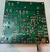
I've checked all of the solder joints and tested everything for continuity and looked for solder bridges, and found no faults.

Another thing that is not the same is using 20VDC instead of 24V (though the schematic indicates the PS is providing 22VAC). I can see If it can find something that goes up to 24VDC at work, or alternatively I've got a variac and could supply 24VAC at pin 12. Don't know if this would make any difference, but it is one thing that different.

I did also pull the cover off the speaker relay just to make sure things were moving freely.

Obviously this is frustrating, and I feel bad that you are taking so much of your time assisting to find the issue. I'm sure if you had the board in your hands, you'd likely find the problem quite quickly. Troubleshooting form a distance can be very challenging. Thanks again for your assistance!
 
Last edited:
Back
Top Bottom