• The move to the new server is done. There are some software and database maintenance updates in process. This has us passing the hat around to help out. We appreciate any donations. Seriously, even a dollar helps. The payment page may be found here - https://www.audiokarma.org/support.html

Opinions on state of AU-20000 sought

C905 does contribute to the delay time. I don't think C07 has any effect.

If it helps this is a brief description. C10 (+4.7µF) provides an initial delay by acting on TR03, keeping it turned on. When TR03 turns off C905 begins to charge up. Once C905 is charged TR04 will turn on the relay.
Thanks for that. I do like to understand how the circuit is functioning, unfortunately I'm not as well versed in circuits as I'd like to be.

Tested the old 2SC1364 transistors and was measuring hFE in the range 307 - 390. Checked a few KSC1815Y I have on hand instead of pulling the ones on the board and measured hFE of 153 - 163, so definitely quite a bit lower. KSC945 I have on hand are giving hFE of 247-249, which still seems a bit lower than the originals. KSC1845F are 331 - 340, which seems like a better gain match to the originals. I can try 1845 for TR04 and see if that solves the problem.
 
It won't hurt to try, but I think your issue is elsewhere in the circuit. A 2 sec delay is almost like TR03 is not turning on at power up.

Just checking, have you tested all the diodes?
 
It won't hurt to try, but I think your issue is elsewhere in the circuit. A 2 sec delay is almost like TR03 is not turning on at power up.

Just checking, have you tested all the diodes?
Did not test the diodes as things were working normal prior to replacing components. I did just try KSC1845 for TR04, and there was no change in the fast relay click.
 
Can you take a voltage measurement on the base of TR03 to ground, assuming the board is still in the amp? When you turn the amp on you should see a few hundred millivolts slowly falling to just a few millivolts with in a few seconds. It may spike when the relay closes, but then fall again.
 
Can you take a voltage measurement on the base of TR03 to ground, assuming the board is still in the amp? When you turn the amp on you should see a few hundred millivolts slowly falling to just a few millivolts with in a few seconds. It may spike when the relay closes, but then fall again.
I pulled all the connectors to change TRO4, then powered the board via a DC PS as you described to test. Does the board need to be in the amp to measure base of TR03 or can it be done with the external PS?
 
Can you take a voltage measurement on the base of TR03 to ground, assuming the board is still in the amp? When you turn the amp on you should see a few hundred millivolts slowly falling to just a few millivolts with in a few seconds. It may spike when the relay closes, but then fall again.
Did the test, the voltage went to a few hundred mV, then slowly dropped (over about 10 seconds) to around 40 mV where it stayed.
 
Ok, seems to be normal although it's difficult to tell what's happening on the base of TR03 in the short 2 sec window before the relay closes.

Can you try adding some capacitance at C10 by replacing 4.7µF with 10µF on the back of the board to see if that extends the delay time?
 
Ok, seems to be normal although it's difficult to tell what's happening on the base of TR03 in the short 2 sec window before the relay closes.

Can you try adding some capacitance at C10 by replacing 4.7µF with 10µF on the back of the board to see if that extends the delay time?
OK, added another 4.7 µF to C10 to get 9.4 (rather than removing the 4.7 and adding a 10). It did increase the delay time for the second relay. Getting about 3 seconds now. Do I need something higher there?
 
Checked resistors in circuit and nothing amiss there. R15 was reading low in circuit, so lifted a leg to test, and spot on at 100 kΩ. Checked the large black diodes in circuit, and nothing seemed amiss their either. I think one did give a reading in both orientations of the probe, I believe it was D16 but can double check.

Can you replace TR03 with KSC1845 to see if things improve?
Will do.
 
I can't think of any other possibilities at this stage. The components seem to all check out and if you're sure the traces and solder joints are good then you could try increasing the capacitance at C10 and see what it takes to get an acceptable delay time.

Although, it's troubling that we can't pinpoint the issue given it worked before you changed components.
 
I did test each new metal film resistor before I put them in, just to be safe.
The change in behaviour is quite marked, so I am thinking of something quite fundamental that changed after you restored the protection circuit components. The only thing I can come up with is a misplaced resistor? you tested them all 'going in' but are they all definitely in the right places?
 
One other possibility is to replace D17. If it is slow to conduct then C10 won't have enough time to charge. The more charge C10 can hold, the longer the delay time.

Edit: In fact, I think it's time to replace all the 1S2473D diodes in case any are leaky.
 
Last edited:
The change in behaviour is quite marked, so I am thinking of something quite fundamental that changed after you restored the protection circuit components. The only thing I can come up with is a misplaced resistor? you tested them all 'going in' but are they all definitely in the right places?
I agree, my gut tells me the issue has to be something I replaced unless something else coincidentally failed. My plan today is to go back over every component I replaced, check for cracked solder joints and any solder bridges I may have caused.

One other possibility is to replace D17. If it is slow to conduct then C10 won't have enough time to charge. The more charge C10 can hold, the longer the delay time.

Edit: In fact, I think it's time to replace all the 1S2473D diodes in case any are leaky.
I do have replacements for those (1N4148, I believe), but will triple check all my work 1st.
 
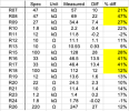
Here's the update. Since I checked all resistor values before placing them on the board, I used the resistor markings to check that the resistors were in the correct positions - they were. Check the resistors as given in the service manual against the printing on the PCB just in case there was an error in the board printing, but found no discrepancies. I then tested all of the old resistors to determine how far out of spec some of them were. It's true the protection board was working before I started replacing components, but it was working with the values of the old resistors. Here's the table of values. I've marked the ones farthest out of spec in yellow. Also, where there are two or three identical resistor values, I don't know which was in which position, so those could be swapped.

Screen Shot 2026-09-12 at 11.51.23 AM.png

Maybe the out of spec resistors where "hiding" problems from other out of spec/failing parts? Other tests I should look at, or is it time to look at/replace the diodes?
 
Back
Top Bottom