richardpp
Well-Known Member
4. A comparison between a BA-3000 and the amp section of the AU-20000 is intriguing. To my eyes, the amps are the same (same design, same boards) yet for some reason bias on the BA-3000 is set at 20mA (20 mV measurement), while the AU-20000 is set at 35mA (35 mV measurement). The wording on the service manual pages for setting bias in each unit is identical (down to misspellings!) except for the bias current. The only difference I can see is a difference in the value of the dropping resistors on the BA-3000 (330 Ω) vs. 220 Ω on the AU-20000. In @Leestereo 's restoration thread of a BA-3000, the dropping resistors are mounted on the PS board, but the original design only used a single 330Ω/5W resistor vs. a combination of 3 resistors on front and back of the board in the AU-20000. I assume the lower bias current setting in the BA-3000 leads to less heat generated, but it would be interesting to have some quantitative data. I know I'm missing something regarding what's happening with F-2508 in the two units. The schematic shows ±85V input to the board and ±65/±35V output from the board in both SM, so I'm not understanding why the difference in dropping resistors and bias settings. OT's are the same, power out put is the same.
The difference in the dropping resistors can be explained by the differing demands placed on the regulator. In the AU-20000, the entire control/ preamp section i.e. phono, eq, tape, filters etc., runs on 35V. The BA-3000 in comparison has far lighter duty, i.e. filter and meter circuits.
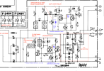
The BA-3000 has 330Ω/5W resistors in the low voltage regulator. The schematic indicates a theoretical voltage drop across the resistors equal to 11V, representing a current draw of ~33mA. This compared to the AU-20000 which has a measured current draw of ~120mA. To adapt the regulator to the increased current draw Sansui decreased the value of the dropping resistors. The schematic show the value at 270Ω, (150Ω + 120Ω). In actual fact, with the addition of 1.2KΩ parallel resistors on the conductor side of the board, the value became 220Ω.
The bias setting of 20mA comes from the BA-3000 service manual. Although the development of the BA-3000 moved forward in conjunction with the AU-20000, to my knowledge the manual was never updated. Developments included the 'dash one' driver board (F-2507-1), a revision which routed unregulated power to the pre-drivers in place of the regulated supply. Another significant development was a new emitter resistor board (F-2497) for the AU-20000 with a physically larger layout than the older (F-2509) belonging to the BA-3000. In short, I think the 35mA bias spec of the AU-20000 could apply to any BA-3000 with the above production changes but otherwise, without them, I would keep it to 20mA.
Finally, both models got an updated driver board, re-designated F-2507, that saw the bias compensation transistor moved from its old location on the output heatsink to a new location on the driver heatsink. I found this change to have a substantial improvement in thermal stability. I think the tendency for the bias to creep in the older units meant that they ended up running quite hot. I'm still trying to find out when this change was made. I suspect it was fairly early on looking at the number of examples on the web that have the new boards. The development of the AU-20000 from the BA/CA 3000 combo may have been a little troubled in the beginning, but I think by early (to mid) production I would give the AU-20000 its due.
Hope this helps.
Last edited:


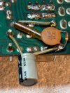
 I was lucky I did not inadvertently snag that thin copper and break it. Need to get the epoxy out!