• The move to the new server is done. There are some software and database maintenance updates in process. This has us passing the hat around to help out. We appreciate any donations. Seriously, even a dollar helps. The payment page may be found here - https://www.audiokarma.org/support.html

Yamaha M70 ZDR

Register to hide this ad
I am using the QA403 for THD measurement.

In the calibration procedure for the ZERO distortion circuit, it states to measure THD at DIST and E. This is not possible with the QA, when I move the INPUT leads to this location it instantly blows the Main PS 15A fuse.

At first I connected the QA to the SPKR terminals and ran the THD test, no matter how I adjusted the VR’s the value didn’t change. So I thought maybe I should move the QA Inputs to the DIST test locations.

Now I am thinking that what I should be doing is measuring DCV at the DIST locations and adjust to 0.00vdc?
 
With the Distortion Analyzer Output connected to Main IN
With the Distortion Analyzer Inputs connected to SPKR Lug

1697816757121.png
 
With two DMM's connected to the DIST and E test points I am able to adjust VR101 & VR102 to a minimum of 0.01vdc
I don't understand what Yamaha is expecting to set these values to? Or if this is even a valid way to set the ZDR circuit?
 
So I decided to pull the QA from the unit.
Connected SPKR's to the SPKR lugs
Nothing connected to the MAIN IN

Power on: Loud hum

Connect a cable to the MAIN IN and the AMP runs to -32db and much louder hum to the SPKR's

Connect a cable to the MAIN IN on the AMP and output of Signal Generator (output turned to 0 ) runs past +2db and outrageous hum to the SPKR's

All of this testing is with the AMP volume controls set to minimum!
 
Distortion meter with input as per sm.
Apologies, my previous post was unclear (=bs), I meant the dist test points with 1Khz sine wave input and 200W into dummy load.

Now I am thinking that what I should be doing is measuring DCV at the DIST locations and adjust to 0.00vdc?
With two DMM's connected to the DIST and E test points I am able to adjust VR101 & VR102 to a minimum of 0.01vdc

DCV does not equate to signal distortion, it's more akin to transistor biasing. Need to minimize the distortion of the 1kHz signal

Others can better advise on how to use the qa403.

I'd switch to a log frequency scale so as to expand the 0-3kHz area.
 
Okay, so if I get this correct:

DMM DC Voltages have no value in this measurement YES

QA Analyzer must be connected at the SPKR Lugs YES

With audio analyzer connected: When I adjust VR101 or VR102 I don't see any change in the THD #'s

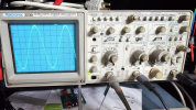
Now I pull the SPKR's off the Lugs and connect a audio signal generator to the MAIN IN and a scope onto the SPKR Lugs:

Do you see anything in this sine wave that is a hum?

1697829901976.png
 
So I decided to pull the QA from the unit.
Connected SPKR's to the SPKR lugs
Nothing connected to the MAIN IN

Power on: Loud hum

Connect a cable to the MAIN IN and the AMP runs to -32db and much louder hum to the SPKR's

Connect a cable to the MAIN IN on the AMP and output of Signal Generator (output turned to 0 ) runs past +2db and outrageous hum to the SPKR's

All of this testing is with the AMP volume controls set to minimum!
So the bad news: The problem is with my bench speakers
DYNAUDIO EMIT M-20
BENNIC XPP 8.2uf 100v Metalized Polypropylene Film
D-18.9mm
L-36mm

Doesn't appear to be a high end cap, nice speakers
I would like to keep,
equal to or better replacement cap ideas?
 
DMM DC Voltages have no value in this measurement YES
There will be a DC voltage at that TP however it is not significant to minimizing the distortion

QA Analyzer must be connected at the SPKR Lugs YES

With audio analyzer connected: When I adjust VR101 or VR102 I don't see any change in the THD #'s
The adjustment is for the ZDR amplifier stage NOT the entire amp, ie, from main in to speakers

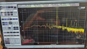
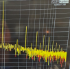
Harmonics appear to be multiples of the main (1kHz or abouts). May be due in part to your signal generator and also amplifier performance, at -40, -50dB seems too high.
 
How this is applicable is beyond my pay grade:

The inputs are 100k ohm, so it’s very unlikely they could trip a breaker in your fuse box. What is more likely is that you have a ground connected one place in your circuit via the BNC shell, and then you connect another BNC shell to a non-ground potential. For exmaple, if you have a QA403 output connected to the amp input via RCA, then you have established the “chassis ground” as 0V. Which is normal.

If you then put a scope probe on a QA403 input, and clip the scope lead ground to a power supply rail, then there’s enough current that can flow through the scope probe leads, through the BNC shells, and back to the chassis ground established by the RCA.

There are also certain types of class D amps where both speaker outputs sit and mid rail. For example, on the TPA3255 Class D amp from TI, it’s a push-pull config, and if you connected to 50V, then both speaker outputs idle at 25.000 volts. So, if you put a DVM across the speaker outputs it reads 0V. But you connect an RCA to the input, and then connect a scope probe ground to SPKR- it will fault. The TPA3255 faults very gracefully, so it’s a bit hard to figure out what is going on at first.

Take a DVM and measure from the RCA input shell to the place you connected the scope ground lead. I’ll bet you read a sizable voltage.
 
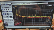
What is creating these Harmonic Spikes?

1697833041231.png
 
In general, to measure/minimize the THD of an amp, the reference input (1KHz sinusoid here) is injected into the input of the amp. The output of the amp is then fed into high power dummy loads (8Ω). A ’copy’ of the output is also fed into spectrum/audio/whatever analyzer through some sort of coupler for observation/measurement, then adjusting the relevant pots will also adjust the THD for the entire amp to the extent that is allowed by Yamaha design, this should be visible on the spectrum analyzer if you have the correct setting for the resolution bandwidth.

You should never feed the amp output (32dBm in this case?) directly into any analyzer unless you’re going through attenuators (20dB or 30dB at least). If you overdrive the analyzer input, that itself will create intermodulation products not to be mistaken with those you’re trying to measure.
 
Back
Top Bottom