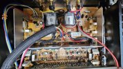
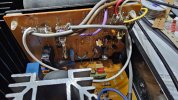
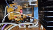
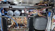
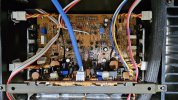
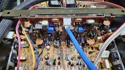
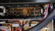
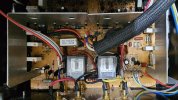
Yamaha5000
Never settle for 2nd best
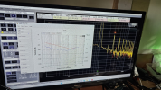
This coupler is external to the QA?fed into spectrum/audio/whatever analyzer through some sort of coupler for observation/measurement,


This coupler is external to the QA?fed into spectrum/audio/whatever analyzer through some sort of coupler for observation/measurement,

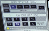
Yes. Refer to your analyzer’s manual to find out the max input sig level, it may be marked on the front panel too.This coupler is external to the QA?
dB what? dBm? dBu? dB something else? dB by itself isn’t a unit of anything …42db

 forum.quantasylum.com
That means a max input of ≈125Vrms, that’s pretty high, are you sure? I’m not home now so can’t read lengthy texts but a cursory look at their diagram shows they’re taking CA-2000 ‘rec out’, not the direct output. A power amp has no rec out so you need a coupler.
I’d keep the input to the analyzer at least 10dB, preferably more, lower than the spec to get very linear response without having to worry about causing intermodulation with the analyzer.Last week I measured the RMS with a generator set at 1.6v input and 42v at the output, this was just before clipping. DMM for measuring RMS and a Scope to see the clipping point.
Personally I wouldn’t bother with it unless you’ve made drastic changes to the board (new non-OEM output transistors, etc.). As far as M-70 is concerned, the procedure is a bit unclear to me, does the ZDR adjustment voltages at test points go up and down as you adjust? Do you need to be monitoring the output on an analyzer visually? It doesn’t say.What is your summary of thoughts on measuring the ZDR Test Points?
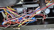
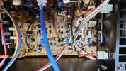
The output transistors were changedyou’ve made drastic changes to the board (new non-OEM output transistors, etc.)