Follow along with the video below to see how to install our site as a web app on your home screen.
Note: This feature may not be available in some browsers.
The move to the new server is done. There are some software and database maintenance updates in process. This has us passing the hat around to help out. We appreciate any donations. Seriously, even a dollar helps. The payment page may be found here - https://www.audiokarma.org/support.html
I stand corrected. Expected to see a lug which is fed a 1Khz square wave (maybe 1-2Vp-p) that's used for probe compensations, it's on my Chi-DSO. See item 18 below, looking for a clean squarewave trace.
Simply probe it like any other test point, don't connect GND clip.
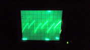
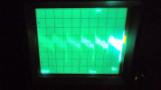
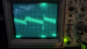
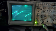
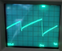
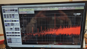
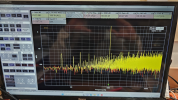
Post #30 pix 2,3 show every second cycle has a significant spike, might be an issue or a problem with an old cro. Maybe keep in mind. This is on the +ve rail.
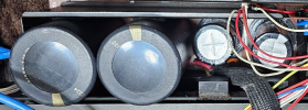
Well! Do you think when Yamaha was designing the mounting method for the Electrolytic and Power Circuit one engineer might have thought " Well Billy Bob that looks darn good to me "
As pointed out earlier, the ripple will depend on the amplifier class and the amps circuitry (=load), so no generic statement can be provided. I've provided oscilloscope traces for my M-70. You have a second M-70. Is the ripple of the amp under test in the same ballpark as your other unit and my unit? If so, all good from a ripple perspective.
I have been unsure of the values on your display, is this the total PPV of the ripple:
My values are 4X that amount"
I thought you stated your M70 was in original condition. With the high end filter caps that I installed in my unit I would think my PPV values would have been less not more.
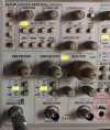
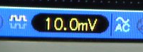
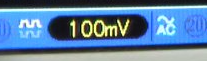
10mV/100mV refer to the Volts per division (grid square).
my p-p ripple appears to be,
HB+ 34mV
HB- 45mV
LB+ 520mV
LB- 450mV
Keep in mind that the circuitry is not symmetrical between +ve and -ve rails so you have different +ve and -ve loading on the caps so you have different ripple on +ve and -ve rails
I have also been able to adjust DIST as I hoped I could, why this doesn't work on the unit #1 is still a mystery.
QA403 Output connected to Main IN
Scope Probe on QA403 Input and DIST Test Point
Was able to adjust VR101 & VR102 and see the real-time results on the QA403 display,
This process allowed the THD #'s to drop below the 0.00% levels
I am still seeing on unit #1 when I connect the QA403 to Main IN and no connection to the SPKR Lugs the M70 runs to max V output 750W upon turning it on. This is also with the M70 Volume Controls set to zero. The QA403 wants to see a return value and when it doesnt it runs to max output V (Main IN). This action is very confusing, thus the reason for hesitation on the connection of the Scope Probe.