Yamaha5000
Never settle for 2nd best
I do have a sincere concern about the harmonic spikes, what to do about them?


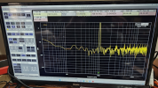

Usually the reason is due to poor grounding, different transistors having different stray capacitances, different gains, etc. . You can try the procedures you have to see if pots adjustments make any visible difference.I do have a sincere concern about the harmonic spikes, what to do about them?
Are you referring to the output transistors?different transistors having different stray capacitances, different gains, etc
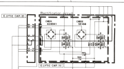
Any transistor in the audio path, from the input to the output. Couple years ago I replaced the OEM op-amps in my Technics tuner with ultra high grade op-amps and ended up with a very annoying and constantly present high pitch howling. Although at higher volumes it wasn’t audible, it was there. It turned out the super op-amps had 110dB gain as opposed to 100dB for the originals. I took the last one in the line up out and gone was the noise. In effect I reduced the gain by 10dB.Are you referring to the output transistors?
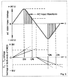
There’s the ripples due to rectification but with proper filtering, yes, those are practically DC voltages. Like anything else, however, if you look at them under a microscope, you’ll see things you didn’t know were there, but they’re generally inconsequential. As long as the harmonics are down by the amount the standards say, all is good. I don’t know about audio standards but for cellular band, for example, the harmonics (second, third, and their first order intermods) must be down by 42dB or so wrt the main signal.Would it be correct that HB+, HB-, LB+ & LB- would be a constant DC voltage with no AC component?
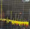
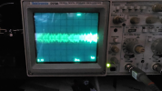

I don't see a connection between ripple and audio harmonics if that is what you are suggesting.First harmonic is around 34db, second harmonic 48db, third harmonic 52db
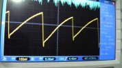
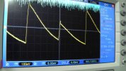
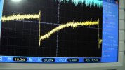
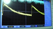
The photo was not good but it was set to 2mshe HB+ and LB+ traces are gibber-ish, set time scale to about 1-5mS, looking for a 120Hz "sawtooth sine" waveform

My stupidity! I don't have a Main IN or Spkr load connected!The ripple is caused by the amp(load) running down the stored energy in the caps when the input (rectified) charging voltage is low. Generally class A amps will have higher bias and run down the stored cap energy quicker so higher ripple.
No, I did not mean a spkr load. I was referring to the amps circuitry as being the load on the rectifier/main filter caps.My stupidity! I don't have a Main IN or Spkr load connected!
For an unregulated supply I previously would have thought that is ok. I'm surprised the ripple on my unit was so low, might be a measurement error on my part.Error should have stated 0.2vpp
Remove the base plate and measure at the solder joints for the main caps. Larger caps are +/-HB. Smaller caps are +/-LB, as normal, cap common pin is GND. The "sawtooth wave" is there, if you can't see it clearly then you have an oscilloscope/tools problem, don't blame the amp.But shouldn't I see this sawtooth wave?
I am not seeing anything like you have shown on your scope.
I am not familiar with that terminology1Khz lug