• The move to the new server is done. There are some software and database maintenance updates in process. This has us passing the hat around to help out. We appreciate any donations. Seriously, even a dollar helps. The payment page may be found here - https://www.audiokarma.org/support.html

Genesis Physics Speakers:Model II

IMG_20190605_141121010.jpg

Pulled out the passive on one speaker today. Passive was original, w00t. This is what my particular crossover looks like under the batting.
 
So, at this point I'm contemplating recreating the entire crossover board with new wiring... I'm kinda thinking "go big or go home" on this, my first project (lol). I'm getting my parts together at Parts Express, and have decided to go upper middle on components.
Finally, I think I finally wrapped my head around the crossover, how its all connected... this stuff isn't something I have a lot of experience with, so it took some staring and mumbling to myself.
(here's the crossover schematic for Genesis Model 2 (ii) first generation: http://www.humanspeakers.com/genesis/gen2.htm#xver)

Let me break it down and see if you experts agree with me:
1) positive and negative binding posts -- speaker wire connects to these from the outside
2) from the positive, one wire (red in my photo above) goes directly to the Woofer; another wire (pink in mine) goes to the 2 pole switch
3) the switch has a 10uf capacitor on the other terminal; when the switch is closed, the current runs straight to the cap; the switch ALSO has a resistor (2ohm/5 watt, i think) that connects to both switch terminals; when the switch is open, the current is forced to run through the resistor, and then to the capacitor (i was not sure about this at first.. do i have it right?)
4) In mine (photo above) the cap then connects to a pink wire (which goes to tweeter, I think?), and ALSO to one lead on the inductor;
5) the other lead on the inductor connects to three (?) negative wires; one runs to the negative binding post; the other two lok like they're joined at first, but I'm guessing split up to connect to the negative terminals on the woofer and tweeter...

Am I missing anything, or get anything wrong?

Finally, generic questions, because I am such a newbie to this:

1) The resistor... if I'm understanding the Human Speakers schematic correctly, this is a 2ohm / 5W resistor... do i have that right? Given that, does it matter at all WHAT KIND of resistor? Metal oxide film, or cement ceramic? (PE doesn't seem to carry 2ohm/5 W resistors anymore... probably not very popular).
2) what are the terminal connector tab things called, that you put at the end of a wire and connect to the tabs on the woofer? I haven't stumbled on their proper name and can't find them on Parts Express because of that..
3) DO i need any special kind of hot glue/adhesive, or do generic hot glue sticks from the craft store work fine? I won't damage any components with their initial heat? should I used zip ties in some kind of board instead? any concerns I should be aware of with that?
4) Does the inductor have negative positive leads, or does it not matter which ends I connect to which other wires?
5) Is it worthwhile to use better internal wiring, like 16awg, to connect everything up?
6) in my photo above, there is a little black bar thing, with solder points at each end... its connecting the inductor to the other wires... what is this thing called? is it useful to connect everything like this, or should i just solder all my leads together directly and avoid that sort of bar connector?
7) CAn I glue that fancy inductor I'm buying down, or should I zip tie it, since its "impregnated" with special wax?
8) Should I do anything to keep the fibgerglass batting from directly resting on the crossover?

And yes, this is getting a little pricey for a hobby, lol, but i figure... I was prepared to spend about $200 - $250 for some brand new speakers... with the parts I'm ordering, I'll be able to fix both these Gensis 2s, and a pair of KLH Model 20s I also picked up recently.. fingers crossed. And all will still be under the price I was expecting to pay for one set of new speakers, and I've also kept awesome vintage equipment out of a landfill in the process :)
 
Last edited:
Finally, generic questions, because I am such a newbie to this:

1) The resistor... if I'm understanding the Human Speakers schematic correctly, this is a 2ohm / 5W resistor... do i have that right? Given that, does it matter at all WHAT KIND of resistor? Metal oxide film, or cement ceramic? (PE doesn't seem to carry 2ohm/5 W resistors anymore... probably not very popular).

Don't know. I don't bother replacing resistors unless they are bad. I have not had to replace any bad resistors.

2) what are the terminal connector tab things called, that you put at the end of a wire and connect to the tabs on the woofer? I haven't stumbled on their proper name and can't find them on Parts Express because of that..

Don't know. These, perhaps? https://www.parts-express.com/gold-12-awg-1-4-female-disconnect-5-pair--095-810 But they require crimping, which requires a special tool to make a good solid connection.

I don't bother replacing internal wiring and I reuse the originals 'cuz they have always been attached to the wires.

3) DO i need any special kind of hot glue/adhesive, or do generic hot glue sticks from the craft store work fine? I won't damage any components with their initial heat? should I used zip ties in some kind of board instead? any concerns I should be aware of with that?

Normal hot glue is often used. When gluing caps, it is important to know that high heat damages caps. So avoid using too much hot glue or applying it for too long. The heat from hot glue is one reason many use tie wraps to secure components. I use enough hot glue to secure the cap and let it quickly cool.

4) Does the inductor have negative positive leads, or does it not matter which ends I connect to which other wires?

Inductors do not have polarity. When there is more than one in a crossover, their relative location is important. That is not an issue here.

5) Is it worthwhile to use better internal wiring, like 16awg, to connect everything up?

"Better" internal wiring is a personal preference. There is no technical reason to replace internal wiring that is not damaged or corroded. Therefore, there is no "better." The lengths are short and the factory installed wiring is adequate. Many replace with thicker gauge wiring just because.

6) in my photo above, there is a little black bar thing, with solder points at each end... its connecting the inductor to the other wires... what is this thing called? is it useful to connect everything like this, or should i just solder all my leads together directly and avoid that sort of bar connector?

I believe you are referring to a terminal strip. A terminal strip aids in terminating components and wiring. There is no reason to remove the one in there. Just re-use it.

7) CAn I glue that fancy inductor I'm buying down, or should I zip tie it, since its "impregnated" with special wax?

Whatever you want to do. The original is glued in place. No reason not to glue the new one. I don't know about any fancy wax. Some manufacturers coat the windings in was as a way to secure them. If that is the case, hot glue may not stick to the wax. A perfectly fine inductor would look just like the one you have pictured: wire on a spool. No wax required.

8) Should I do anything to keep the fibgerglass batting from directly resting on the crossover?

Nope. Fiberglass will not be affected by any heat generated by the crossover. Just put the stuffing back the way you found it.

Other than the binding posts and the caps, there is no technical reason to replace anything else unless it is damaged or broken. Also, if you must replace that perfectly good inductor, make sure you get one with the same size wiring. Thicker coil wire is not necessarily "better." If you change the coil winding wire thickness you will need to take into account the inductor resistance when replacing it.
 
@RTally , it sounds like you're suggesting I may be overthinking this... you are probably right :) Any advice on getting that glue off the backside of the terminal? just chip away at it, or some other method you use so I can remove the old spring clips and rewire to the new binding posts in the same place?

Thank you again for all your guidance; I'll pare down my possibly overzealous shopping cart for the time being and use the stock inductor, etc. ;) I was reading another person's post on how they had upgraded to a foil coil inductor and the high end cap from Jantzen and 16awg wiring, and how performing all those upgrades made these speakers the best of his pretty impressive collection. I think I just got caught up in that daydream :)

I'm also worried about just being unable to un-solder the old cap and terminals, and resolder the new ones in... hence my drift towards building an entirely new crossover set.
 
@RTally , it sounds like you're suggesting I may be overthinking this... you are probably right :) Any advice on getting that glue off the backside of the terminal? just chip away at it, or some other method you use so I can remove the old spring clips and rewire to the new binding posts in the same place?

Thank you again for all your guidance; I'll pare down my possibly overzealous shopping cart for the time being and use the stock inductor, etc. ;) I was reading another person's post on how they had upgraded to a foil coil inductor and the high end cap from Jantzen and 16awg wiring, and how performing all those upgrades made these speakers the best of his pretty impressive collection. I think I just got caught up in that daydream :)

I'm also worried about just being unable to un-solder the old cap and terminals, and resolder the new ones in... hence my drift towards building an entirely new crossover set.

Sometimes it is fun to overthink things. It is also a learning experience the first few times you rebuild anything.

My suggestion would be to do this in stages. Recap and replace the terminals. Listen to them for a while. If you think they could be better, go back in and do some more. If they sound great, sit back and enjoy them. Remember, most people think that any change they make improves the sound.

As for the glue covering the back of the speaker terminals, my first choice is to use a putty knife that has a wedge (sharp) edge. Depending upon the glue used, it often lifts or chips away from the substrate. I usually end up destroying the original spring clips when I remove them. I don't care because they go in the trash.

You may have to cut the wires where they go into the glue because you may not be able to clean off the glue from the soldered connections to unsolder them. It is best to have a clean wire when using solder, so cutting is fine. It looks like you should have enough wire length to cut them if you cut close to the glue.
 
Last question for the day, I promise... where the screws for the drivers go in, the MDF is starting to chip apart. My first thought was to put some wood glue in to hold the holes together and give the screws some new material to bite into. Am i on the right track there? Thanks, a last time in this 24 hour period :)
 
Last question for the day, I promise... where the screws for the drivers go in, the MDF is starting to chip apart. My first thought was to put some wood glue in to hold the holes together and give the screws some new material to bite into. Am i on the right track there? Thanks, a last time in this 24 hour period :)

There are many solutions to that problem. Pick one that you like:

One solution is to glue a backing piece of wood on the inside of the baffle and use longer wood screws.

Another solution is to epoxy in T-nuts or similar and use machine screws. This is good if you plan to repeatedly remove the driver.

Yet another solution is to glue a wood matchstick or wood sliver in the hole. This has the advantage of replacing some of the missing wood particles.

Often the easiest solution is to rotate the driver and drill new pilot holes where the baffle is solid. Just make sure that the old holes are sealed so that there are no air leaks.
 
I've enjoyed following this thread. Looks like I need to check up on the caps in my '79 1+'s, and '80's 110's. I replaced the surrounds years ago, they appear ok.
 
My EPI 100 woofers arrived recently, they look pretty nice :) And I stopped hemming and hawing and put in my Parts Express order for the parts I need for the Genesis 2's (and for my KLH 20's)...getting excited about making these speakers sing again :)
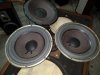
I also successfully used my shop vac to mostly fix the poked in dust caps on the Passives.

I noticed that there isn't as much travel on my second hand EPI woofers as there was on (suspected) Boston Accoustics drivers that came in my Gen. speakers... does that line up with the experiences of other Gen. owners?

Gen-Phys-ii-EPI100-woofer.jpg
 
My EPI 100 woofers arrived recently, they look pretty nice :) And I stopped hemming and hawing and put in my Parts Express order for the parts I need for the Genesis 2's (and for my KLH 20's)...getting excited about making these speakers sing again :)

I also successfully used my shop vac to mostly fix the poked in dust caps on the Passives.

I noticed that there isn't as much travel on my second hand EPI woofers as there was on (suspected) Boston Accoustics drivers that came in my Gen. speakers... does that line up with the experiences of other Gen. owners?

View attachment 1533609

Genesis made their own woofers and tweeters. The long excursion is normal for Genesis. My 66's 8" woofs have a peak to peak of 3/4". Same for the Genesis Is and 11s I've owned in the past. Once you're finished with this project, I'm sure you will be very happy with those IIs.
 
Genesis made their own woofers and tweeters. The long excursion is normal for Genesis. My 66's 8" woofs have a peak to peak of 3/4". Same for the Genesis Is and 11s I've owned in the past. Once you're finished with this project, I'm sure you will be very happy with those IIs.
I'd like to see a pic of your 66's please .
 
I'd like to see a pic of your 66's please .
Genesis 66 (1).JPG
They are the series 1 circa 1986. The woofs were replaced with rebuilt Genesis drivers courtesy of LRS (now Human Speakers). 8" 2 Ohm wired in series (x2), Vifa 3" dome mid and Genesis fabric inverted dome tweet. 4th order linear phase crossover with all air core inductors. I replaced the caps and wiring back in 2004. Ported in the rear with a claimed -3dB point of 28Hz. Have served faithfully and sounded great in my "shop" system for over 15 years. Sure, there are better speakers out there, but I'd have to spend big bucks to top these.

They are a bit piggish with amplifier power and are nominally rated 4 Ohms. The Kenwood L-07MII in the photo has since been replaced with an Adcom GFA-5800 that is kind of overkill, but drives them with ease. I don't listen at high levels, so it's more about control than volume. The lows are clean and extended (no thump, thump). Too bad Genesis Physics closed it's doors in 1987 and never got the press they deserved.
 
Last edited:
Quick project update from me, on my Gen 2's --
I removed the old woofer, passive and tweeter from speaker 1. in the process, one of my "tabs" broke on the tweeter... it seemed to be pretty weak already; and when I attempted to remove the wire from the tab, the tab snapped off at its base.

Now, my intuition here says I can fix this by gluing the tab back down, and then creating a solder contact with the negative wire coming off the tweeter into the tab.. does that sound about right? (photo is BEFORE i broke the tab off)
gp-2-tweeter.jpg


I also decided to remove the old spring clip terminals. I first broke the old glue off the inside of the speaker; then de-soldered the wires connected to the terminals on the inside.

gp-2-terminals-glue.jpg

Then, using a small screw driver and hammer, tapped the rivets on the back of the connectects, from inside the speaker.

gp-2-terminals-out.jpg

I then took a drill/utility knife and expanded the holes left behind to fit my new terminals, which were larger. Doing this encroached on 'newington, nh' line on the board, but nothing I could do about that. I also expanded the holes a little TOO much, so I'll need to fill them a bit with glue or caulk after I've dropped the new terminals in.

(side rant, its annoying that you don't get proper screws when you order terminals from Parts Express).
 
IMG_20190806_213208559.jpg

New posts screwed in. You can see where I got carried away enlarging the holes peeking out above the post strip. :/
 
Back
Top Bottom