
Beautiful amigo! Just plain beautiful!


Beautiful amigo! Just plain beautiful!

Is that a newer version of the idler? Mine hasn't such a wide rubber lip
Not rubber. It’s a harder silicone like material. No idea what its actually made of though.Is that a newer version of the idler? Mine hasn't such a wide rubber lip
Yes, that is exactly the premise I am using and new parts is the last resort. In my way of thinking, this tt has not had a very rough life at all and I know how my Dad took care of it and how I've handled it since acquiring it. There must be something that I'm overlooking or not doing quite right, and I think all roads lead to the idler or the motor. I can't see how the motor isn't properly connected/wired because he bought it straight from Dual, and Dual provided it directly to the Audio Clubs in Germany that US soldiers were buying them from. One typically used a transformer as Germany has 220volt supply, or as in this case where the option is available, a simple switch gets rotated between 110 and 220 and it is currently set to 110 because when my Dad last used it, he had moved to the States and therefore it was 110v. Maybe turning that switch back and forth between 220 and 110 is a good idea? Could knock a little oxidation off of the contacts, hit it with a little Deoxit D5 while I'm at it......no? Clean the on/off contacts while I'm at it also seems logical as someone else mentioned earlier in either this thread or the other one.....Personally, I’d try and chase down your issues a little more before wholesale throwing parts at it.
Sort out your motor issues (from other thread) first and then start chasing the lowest numbers you can pull.
You can easily throw a couple hundred bucks in new parts at it and it get no better….
I have not "sanded" the idler very much, just very lightly touched it to some 220grit sandpaper that I mounted on a small block of wood to give me a hard and consistent backing surface for it. I touched it to the spinning idler, mounted (very gently) on my drill until I just saw a bit of a dark streak forming on the sandpaper and then backed off, repeating this process maybe 3-4 times. I'll see if I can't get a close-up pic of the idler.Have you “sanded” the idler much?
The motors are “constant speed” (or are supposed to be) and the differences in hz are accounted for in the “pulley” (Ie: the cone on the shaft). Different diameter cones for europe and NA power (60hz vs etc).
If you have reduced the diameter of the idler wheel, you change the ratio between the idler wheel and the pulley.
Other than that, I’d go back to the speed change mechanism. More so if you had that apart. The speed is changed and fine tuned by moving the entire idler assembly up and down the pulley “cone”. If its hanging up or not moving properly, its not going to ride on the appropriate diameter of the pulley cone.
I hope that makes sense because its hard to describe in words what makes sense when looking at it…

YES!!! And that's what I've been saying all along, that in order for me to get the right speed, I have to adjust the pulley so far upward that the idler touches it at the "step" separating the speeds. When it does that, it makes sense that things get wonky in terms of W&F it would seem as the speed changes, sometimes pretty drastically like from 33.38 to 35.84 without me doing so much as touching the thing. I have concluded that this is due to the idler moving into that step and out of it, higher speeds when it's in there and lower as it finds the smooth area of the cone again. Hope that makes sense, but if you look at your idler you will see the steps I'm talking about and how they are separated by a very smallish "ridge," for lack of a better term to call it.....If its hanging up or not moving properly, its not going to ride on the appropriate diameter of the pulley cone.
Unless the brass pulley has a silly amount of wear, it was machined that way.YES!!! And that's what I've been saying all along, that in order for me to get the right speed, I have to adjust the pulley so far upward that the idler touches it at the "step" separating the speeds. When it does that, it makes sense that things get wonky in terms of W&F it would seem as the speed changes, sometimes pretty drastically like from 33.38 to 35.84 without me doing so much as touching the thing. I have concluded that this is due to the idler moving into that step and out of it, higher speeds when it's in there and lower as it finds the smooth area of the cone again. Hope that makes sense, but if you look at your idler you will see the steps I'm talking about and how they are separated by a very smallish "ridge," for lack of a better term to call it.....
Here you go, not sure if much can be gleaned from it but just in case:I'll see if I can't get a close-up pic of the idler.
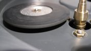
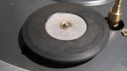

Absolutely agree but I don't have a lathe.....wish I did!However, it is possible you’ve given the “tire” a very slight “out of round” by doing the sanding by hand in a drill. That would drive up the wf. Although it may feel like you’re giving constant pressure, our muscles just don’t work that way. They “pulse”. I chuck things up in the lathe if I want to make something “round”. My hand pressure just can’t match that kind of precision.
One of the advantages of being a “mechanical” guy I guess.Absolutely agree but I don't have a lathe.....wish I did!

Yes, there is a set screw on the side of the pulley that allow for removal. Then, there is a screw in the top of the pulley that allows one to raise and lower the pulley and set, permitting repetition of settings and keeping things somewhat controlled. It's a really nice concept and works well. Are you sure your 1229Q didn't have that little (very small and in a hole in the top of the pulley) adjustment screw on top?A thought: does the motor pulley have a set screw holding it in place? If it does, have you disturbed it? Just another guess, but it may be possible the pulley is out of place. Iirc on my 1229q, its just “bottomed” on the motor shaft and tightened in place.
Also, was the table always running like this or is it only after you took some of it apart and reassembled?
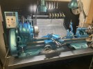
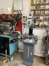
Well, it wasn’t an overnight process. You’re looking at the end point of a 60 year arc of learning, wrenching and accumulating the equipment I needed for the hobbies I wanted to do. Been a fun ride and now, if I can’t buy it, I build it!Totally sick!!! And I'm green with envy, especially that you have the knowledge and understanding to use all of that equipment! Really nice setup there Herr tourmax! And great work with that arm tube.....that's real AK at work!
Yes, there is a set screw on the side of the pulley that allow for removal. Then, there is a screw in the top of the pulley that allows one to raise and lower the pulley and set, permitting repetition of settings and keeping things somewhat controlled. It's a really nice concept and works well. Are you sure your 1229Q didn't have that little (very small and in a hole in the top of the pulley) adjustment screw on top?


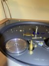
That doesn't matter.If you have reduce the diameter of the idler wheel, you change the ratio between the idler wheel and the pulley.

That's why it's called an Idler Wheel (gear).That doesn't matter.
The idler can be any size, it directly transfers the motion of the pulley to the rim.
Do the math. regardless of the ratio of idler to pulley or the ratio of the pulley to rim, the ratio of pulley to rim is what matters. Call the idler 1 in both cases.


